1561
Necessity for detuning large volume coils?1UMC Utrecht, Utrecht, Netherlands, 2MR Coils BV, Zaltbommel, Netherlands, 3Oxford Centre for Clinical Magnetic Resonance Research, University of Oxford, JR Hospital, Oxford, United Kingdom, 4Wolfson Brain Imaging Centre, University of Cambridge, Cambridge, United Kingdom
Synopsis
Implementing diode detuning on transmit coils is complicated and leads to a loss in efficiency on the transmit side. It has been common practice to include it nevertheless with the aim of preventing loss of receive efficiency and noise correlation between receiver through coupling via the body coil. However, nowadays, receiver coil elements are orders of magnitude smaller so flux linkage is intrinsically low. Moreover, the operating frequency is high to maintain strong tissue-loading, and finally preamplifier decoupling is applied to reduce the effects of mutual coupling. Here we show the coupling to receiver arrays for three non-detuned body coils.
INTRODUCTION
Diode detuning is implemented on receive-only coils as a safety precaution in transmit mode (SAR limitation). Similarly, standard practice has been to also implement diode detuning on transmit coils to detune them during receive mode so as to prevent loss of receive efficiency, and prevent noise coupling between receiver coils through the transmit coil1,2. However, this detuning circuitry is not without a cost in transmit efficiency, which is highly valuable particularly in X-nuclear MRI, as flip angle scales with the gyromagnetic ratio. Usually, the diode acts as a gate which switches an inductor chosen such that it resonates with one of the coil’s tuning capacitors acting as a high impedance which in turn detunes the coil. Diodes, depending on the model, have significant resistive losses, and also interfere with tuning due to their associated junction capacitance which may exceed 6pF. Implementation of detuning is usually performed post-tuning birdcages and often leads to moving the structure off-resonance. Furthermore, diodes may be ill-suited to very high power handling, as is required in body coils, necessitating the use of complicated detuning circuitry. All these additional steps compromise the design and build of large-volume birdcage coils. This abstracts questions the necessity for detuning a body coil birdcage for 31P at 7T. It is hypothesised that the flux emanating from a large (approximate dimensions- length: 40cm, diameter: 60cm) volume coil which couples into a tissue-loaded relatively small receive loop (dimensions-length: 7.5cm, width: 5.5cm) is negligible, and as such, the loss of efficiency and cross talk on the receive side is minimal.METHODS
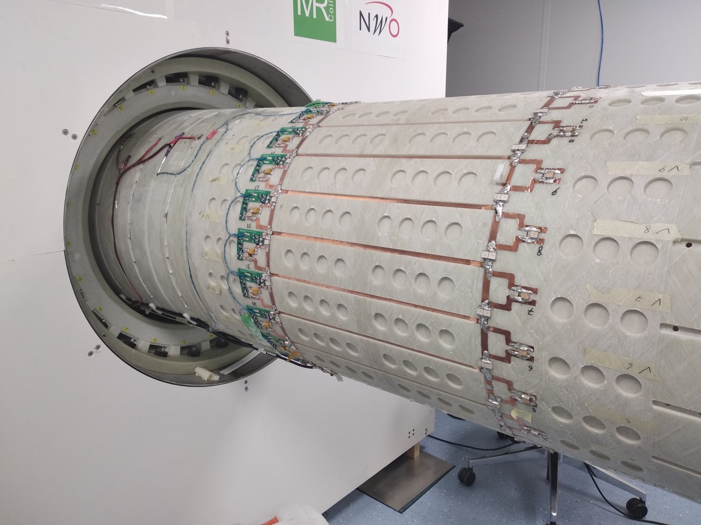
Three versions of birdcages were constructed: one insertable single tuned (120MHz shifted in Siemens 7T MRI)3; one integrated single tuned (121MHz integrated in Philips 7T MRI)4; and one integrated dual tuned (79MHz and 121MHz in Philips 7T body gradient, fig.1). To verify proper functioning of the body coils, B1 maps (inside the 7T MRI systems) and S21 pick-up coil B1 calibrations were performed and compared between the setups. A 30-channel 31P body receiver array composed of eight times 3 or 4 slightly overlapping elements was assessed for noise correlation, with and without the presence of the body coil. In addition, S21 measurements were performed between the body coils and each of the 4 elements positioned in worst case (maximum coupling) locations inside the body coil.RESULTS
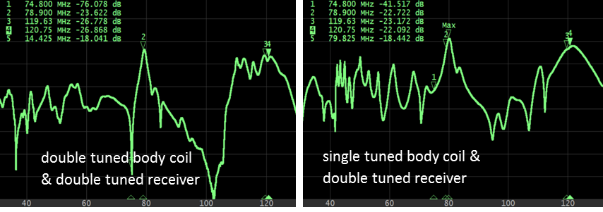
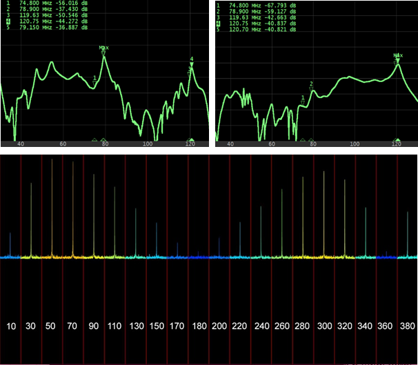
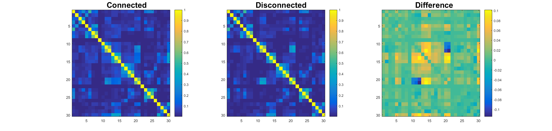
The maximum RF coupling between the receiver array and the body coil was -22dB for the single-tuned coil and -26dB for the double-tuned coil. This was with the receiver positioned closest to the rods incorporating a 2cm distance due to the mechanical housings and matched to 50Ω (i.e. excluding preamplifier decoupling). The B1 level of the single tuned coil was 15μT when driven at 20kW, calculated from the flip angle sweep (fig.2), and 10.4μT driven at 8kW (or 0.8dB more efficient) for the insertable coil3. The B1 level of the double-tuned coil was 4dB less when compared to the single-tuned coil (fig.3). The noise correlation of the 32 channel receiver array inside the non-detunable insertable body coil versus physically removing the body coil was comparable (fig.4).DISCUSSION
The maximum observed coupling between the single tuned birdcage and a tuned receive loop is about -22dB, which is far less than generally reported RF coupling between receive loops. In fact, in the S21 experiments, the receivers were not loaded and not incorporated with preamplifier decoupling and positioned very close to the body coil, so RF coupling in practice will be even lower. The consequence of low coupling is emphasised in the negligible difference of noise correlations between the receiver elements. It should be stated, that for larger receiver coils, the coupling is expected to be stronger.CONCLUSION
Not detuning transmit coils for 31P at 7T leads to only a very insignificant drop in receive performance of state-of-the-art receiver arrays and thus, implementing transmit detuning is not always the optimal approach to transmit coil designs.Acknowledgements
European H2020-FETOPEN: NICI
CTR and LV are funded by a Sir Henry Dale Fellowship from the Wellcome Trust and the Royal Society [098436/Z/12/B]. Hardware funded by a Science Enhancement from the Wellcome Trust (Grant No. 098436/Z/12/A); the EPA Cephalosporin Fund (Grant No. CF 284); the Oxford BHF Centre of Research Excellence (Grant No.RE/13/1/30181).
References
1. Hoffmann, J., Henning, A., Giapitzakis, I. A., Scheffler, K., Shajan, G., Pohmann, R., and Avdievich, N. I. (2016) Safety testing and operational procedures for self‐developed radiofrequency coils. NMR Biomed., 29: 1131–1144. doi: 10.1002/nbm.3290.
2. Avdievich NI. Transceiver phased arrays for human brain studies at 7 T. Appl. Magn. Res. 2011; 41(2): 483–506.
3. Valkovič L, Dragonu I, Almujayyaz S, Batzakis A, Young LAJ, et al. (2017) Using a whole-body 31P birdcage transmit coil and 16-element receive array for human cardiac metabolic imaging at 7T. PLOS ONE 12(10): e0187153. https://doi.org/10.1371/journal.pone.0187153
4. Löring, J., van der Kemp, W. J. M., Almujayyaz, S., van Oorschot, J. W. M., Luijten, P. R., and Klomp, D. W. J. (2016) Whole‐body radiofrequency coil for 31P MRSI at 7 T. NMR Biomed., 29: 709–720. doi:10.1002/nbm.3517.
Figures