1557
Metasurface-based wireless coil to control RF magnetic field distribution inside 1.5T MR scanner.1ITMO University, Saint Petersburg, Russian Federation
Synopsis
We demonstrate a new metasurface-based wireless coil for 1.5T MRI. A simple working frequency adjusting method let using it in a wide frequency range up to 5 MHz that make it compatible with MRI systems of different manufacturers. The design of the coil allows manipulating the radiofrequency magnetic field profile inside the large body coil improving its transceive efficiency in the target area. Phantom imaging with proposed coil approves that by changing the size of the working region is also possible to decrease the excitation power needed to provide optimal flip angle.
Introduction
In clinical MRI large body birdcage coil is used to excite spins in a human body, while local coils are used for MR signal reception. Due to the large dimensions, birdcage coil insensitive to weak MR signals but even such a coil can be effectively worked for reception together with inductively coupled smaller sized metasurface-based structure. This setup allows increasing transmit efficiency of the birdcage coil at some region near the coupled structure1-3. Implementation of metasurface-based devices gives an opportunity to control near electromagnetic field but in very different ways4. Here, we demonstrate a new compact metasurface-based wireless coil for which the spatial profile of the RF magnetic field can be easily adjusted by changing the capacitive loading thus making this device more universal for potential MRI applications.Methods
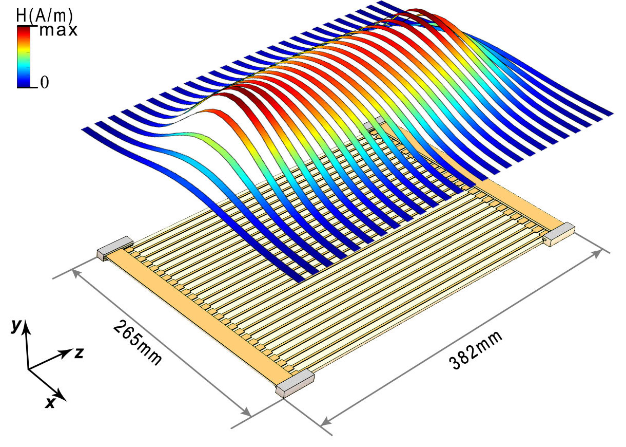
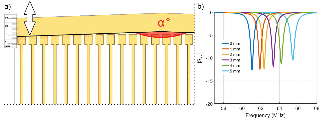
The metasurface-based wireless coil consists of an array of parallel nonmagnetic metallic tracks with miniaturized capacitive loads and two mobile conducting plates at each side of PCB (Figure 1). Each plate can be easily moved along the special rails for adjusting the operating frequency of the structure (Figure 2(a)). PCB substrate, tuning plates, and rails consist of the Rogers4350B material with tanδ=0.0021, ε=3.48. Magnetic field distribution above the structure corresponds to the first fundamental eigenmode5 and schematically depicted at Figure 1. Four different sets of tuning plates with various shapes that determined by angle α (Figure 2(a)) were produced to manipulate RF magnetic field spatial profile across the metasurface. A numerical simulation of the wireless coil was performed in CST Microwave Studio 2017 with rectangular phantom (180×214×57 mm3) filled with water and placed above the structure. MR-images were acquired on Siemens Espree 1.5T MRI system using gradient echo sequence with the following parameters: field-of-view=284×350 mm2, matrix size= 416×512, TR/TE=514/11.1 ms. Birdcage coil was used both Tx/Rx modes. With every change in the metasurface configuration, a system adjustment procedure was performed manually to find the optimal flip angle by varying the voltage of the excitation pulse.Results
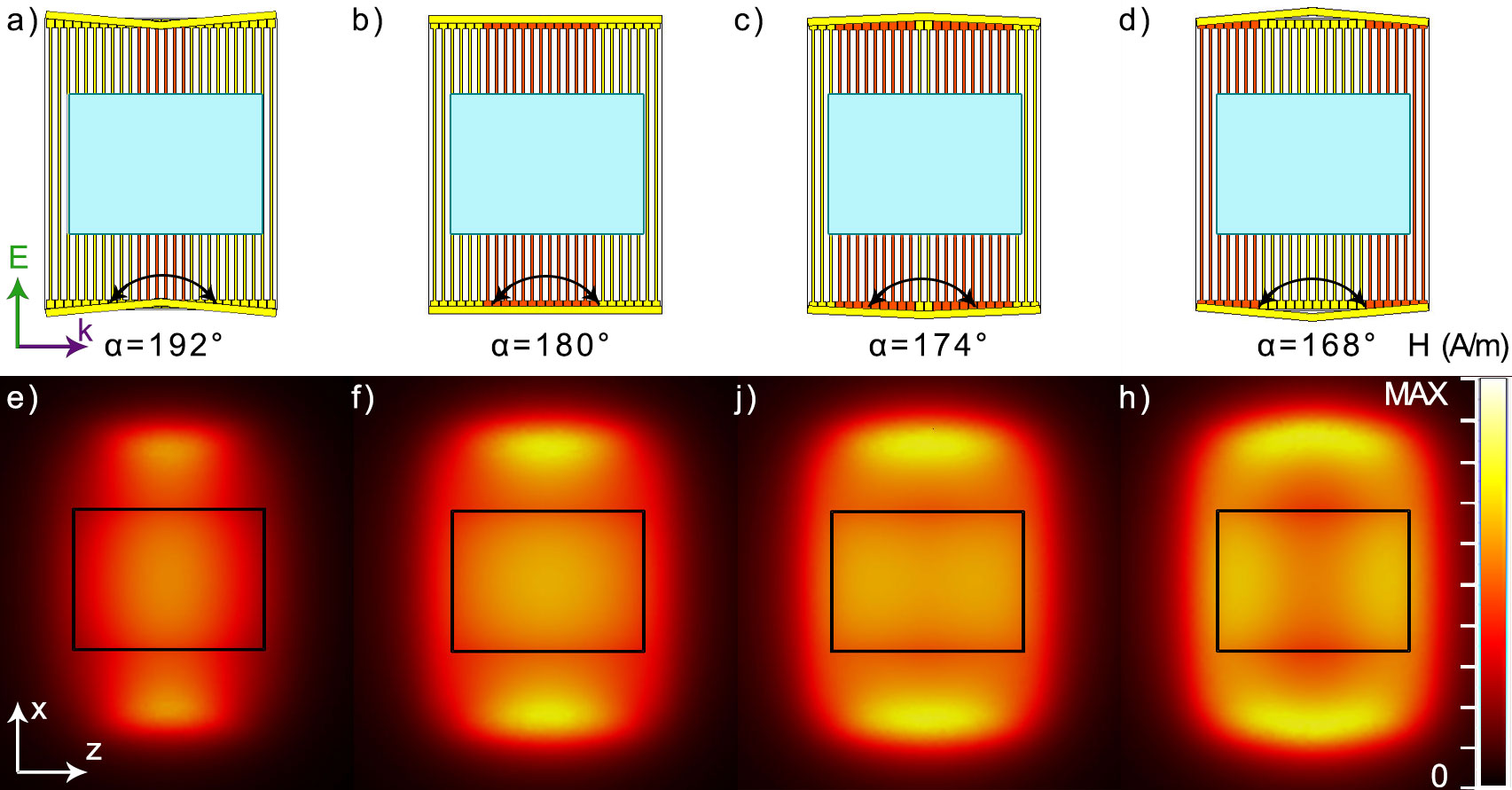
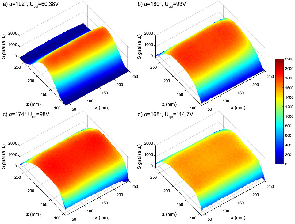
Bench measurements of a coil working frequency dependence from the tuning plate positions were performed by measuring S11 parameters of non-resonant loop antenna placed above the center of the structure (Figure 2(b)). Numerical simulations at CST MWS software shows that by the varying of α (Figure 3(a-d)) leads to the changing the spatial profile of a magnetic field (Figure 3(e-h)). PCB tracks with highest current are highlighted by the red. In the case of α=192º, just several central tracks are prevailing at magnetic field pattern forming. Decreasing the α value leads to an increase in the number of resonant elements but only up to a certain threshold. A further increase of the α ends up with the detuning of the central elements while the edge ones start to form a magnetic loop. In phantom experiments, the signal amplitude in the zone corresponding to the coronal slice of the object was measured at a height of 32 mm from the top of the metasurface and it is shown as a three-dimensional surface at Figure 4(a-d). Due to the changing amount of coupled elements from several at the center (Figure 4(a)) to large groups at the edges (Figure 4(d)), voltage of excitation pulse needed to provide an optimal flip angle is growing from Uopt =60.38V in case of α=192º to Uopt =114.7V in case of α=168º. The most homogeneous signal distribution was obtained with α=174º (Figure 4(c)).Conclusions
We considered a novel thin PCB based construction of the wireless coil for 1.5T MRI with an adjustable spatial profile of the RF magnetic field as well as with tunable working frequency. The proposed design allowing by controlling the amount of the coupled elements of the coil to change the region where transmit efficiency of a standard birdcage coil is increased. Numerical simulations and phantom experiments show that reduction of such region leads to decreasing of overall power needed to provide optimal flip angle. The coil can be used for extremity imaging with the possibility to control the area of efficient transmit efficiency by selecting proper tuning plates set up. Further investigations and in vivo validation of the wireless coil are ongoing.Acknowledgements
No acknowledgement found.References
1. Slobozhanyuk A.P., Poddubny A.N., Raaijmakers A.J.E., van den Berg C.A.T., et al. Enhancement of Magnetic Resonance Imaging, Adv. Mater., vol. 28, p. 1832–1838, 2016.
2. Shchelokova A.V., Slobozhanyuk A.P., Melchakova I.V., Glybovski S.B., et al. Locally Enhanced Image Quality with Tunable Hybrid Metasurfaces. Phys. Rev. Applied, 9, 014020, 2018.
3. Brui E.A., Shchelokova A.V., Zubkov M., Melchakova, I.V., Glybovski S.B. and Slobozhanyuk A.P., Adjustable Subwavelength Metasurface‐Inspired Resonator for Magnetic Resonance Imaging. Phys. Status Solidi A, 215, 2018.
4. Glybovski S.B., Tretyakov S.A., Belov P.A., Kivshar Y.S., Simovski C.R. Metasurfaces: From microwaves to visible. Physics Reports, 634, 1 – 72, 2016.
5. Kretov E.I., Shchelokova A.V., Slobozhanyuk A.P., Impact of wire metasurface eigenmode on the sensitivity enhancement of MRI system, Appl. Phys. Lett., vol. 112, pp. 033501, 2018.
Figures