1555
Investigation of antenna effect on non-contact monitoring of heart and respiration rate1Research and Development Center, Canon Medical Systems Corporation, Kanagawa, Japan
Synopsis
This paper investigates a non-contact heart and respiration rate monitoring with antennas. In order to examine antenna effect on the non-contact monitoring, differences of antenna resonant frequency or antenna type are investigated by experiment. In the experiment, it is found that the higher the antenna resonant frequency is, the easier the heart rate is identified. In addition, it is shown that by using only one open circuit end type dipole antenna, both the heart and respiration rate in spine posture can be identified.
Introduction
Heart and respiration rate are monitored with skin contact electrodes during MRI procedures. However, attaching the skin contact electrodes on a patient leads to patient burden and a decrease in work efficiency of an operator. For reducing patient burden and improving work efficiency, there is a need for a non-contact heart and respiration rate monitoring method. There are some non-contact monitoring methods using a doppler radar system1 or a video motion analysis2, but these methods have difficulties in implementation and costs. A non-contact monitoring method with an antenna near the human body is also reported3, but there is no consideration for resonant frequency and type of antenna. This paper investigates antenna effect on a heart and respiration rate monitoring.Methods
Figure 1 shows the schematic measurement system in this investigation. Reflection or transmission coefficient of two antennas connected with a network analyzer (Keysight Technologies, E5061B) is measured. A subject lies on a bed in a room without an MRI scanner. In reflection coefficient (S11) measurement, one antenna is 2 mm apart on the chest or the back in lying posture. In transmission coefficient (S21) measurement between two antennas, one antenna is 2 mm apart on the chest and the other is 2 mm apart on the back in lying posture. The time response data of S11 and S21 at the resonant frequency of antenna are logged by a computer connected with the network analyzer. Two types of antennas are used. One is a loop antenna that is categorized as a short circuit end type. The other is a dipole antenna that is categorized as an open circuit end type.Results and Discussion
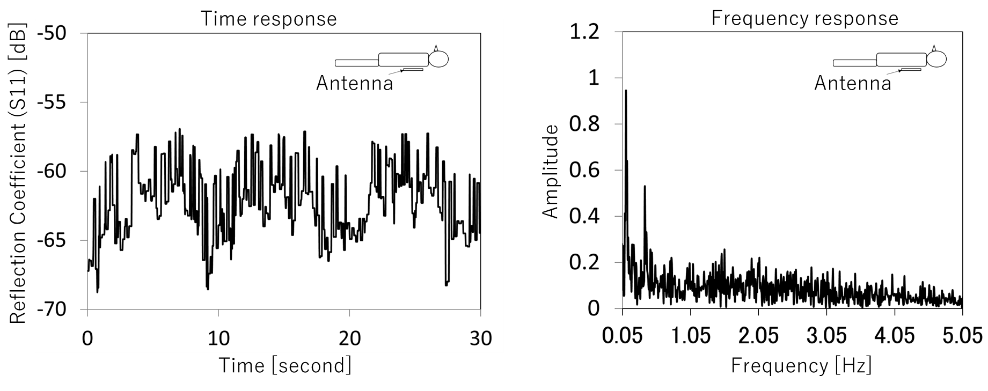
Figure 2 shows S11 measurement results of a loop antenna 2 mm apart on the back in spine posture. The loop antenna resonant frequency is 130 MHz. The time response is composed of some periodical waves including a wave with a period of 10 seconds. The frequency response has two peaks at 0.1 and 0.37 Hz. It is considered that the peak at 0.1 Hz indicates respiration rate and the other peak at 0.37 Hz is noise occurred by body motion. The frequency response also has other signals higher than 0.5 Hz. These signals make it difficult to identify heart rate in time response.
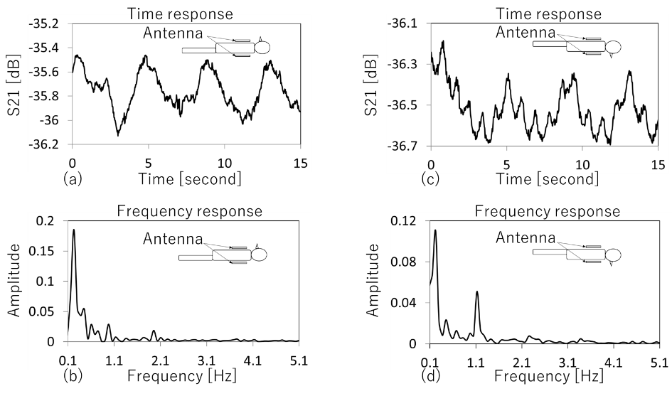
Figure 3 shows time and frequency response of S21 measured with two loop antennas resonating at 130 MHz. The left side of fig. 3 is supine posture results and the right side is prone posture results. The respiration rate of both results is identified easier than that in fig. 2. The heart rate of spin posture result is not identified because the spin posture frequency response has two peaks around 1 Hz. While in the case of prone posture, the frequency response has a peak around 1 Hz. Therefore, it is possible to identify the heart rate in time response.
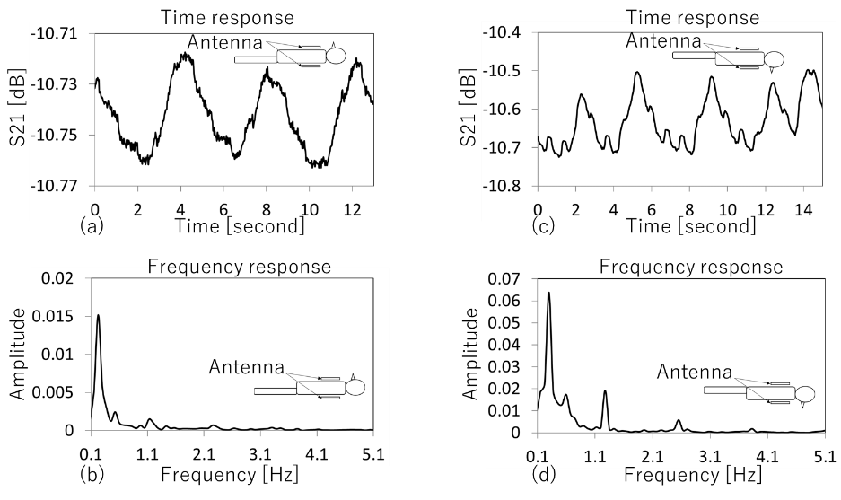
The results measured with two loop antennas resonating at 20 MHz are shown in figure 4. These results are similar to those in fig. 3, but there is a difference. The difference is that the signal variation in time response is small. The small signal variation could lead to failure in the identification of heart rate. From these results in fig. 3 and fig. 4, the higher the antenna resonant frequency is, the easier it is to recognize the heart rate.
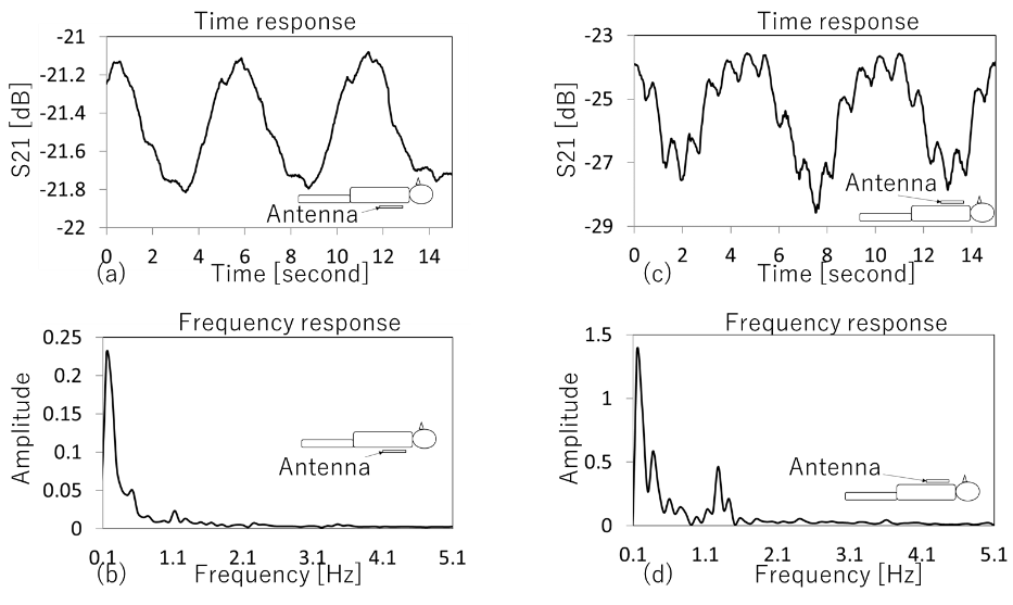
Figure 5 shows S11 measurement results with a dipole antenna resonating at 300 MHz on the back (left side) and on the chest (right side). In the case of attaching the antenna on the back, the respiration rate is identified but the heart rate is not identified, because the frequency response has a peak at 0.15 Hz but not around 1 Hz. In the other case, the frequency response has two peaks at 0.15 Hz and 1.28 Hz and both the heart and respiration rate are identified. From these results, it is found that respiration and heart rate in spine posture can be identified by only one dipole antenna.
Conclusion
This paper investigates a non-contact heart and respiration rate monitoring with antennas. From the results of using two loop antennas, it is found that the higher the antenna resonant frequency used in non-contact monitoring is, the easier the heart rate is identified. In addition, it is shown that by using only one open circuit end type dipole antenna, both the heart and respiration rate in spine posture can be identified. Future work will evaluate the effect of patient motion and MRI scanning on the non-contact monitoring with antennas.Acknowledgements
No acknowledgement found.References
[1] T. Sakamoto et al. Feature-Based Correlation and Topological Similarity for Interbeat Interval Estimation Using Ultrawideband Radar. IEEE Trans. Biomed. Eng. 2016;63(4):747-757.
[2] K. Nakajima et al. Detection of apparent skin motion using optical flow analysis: Blood pulsation signal obtained from optical flow sequence. Rev. Sci. Instrum. 1997;68(2):1331–1336.
[3] Y. An et al. Sensitivity Enhanced Vital Sign Detection Based on Antenna Reflection Coefficient Variation. Biomed. Circuits Syst. 2016;1082):319-327.
Figures