1554
Title: Enhancement of SNR and Sensitivity of Image in MR using Left Handed Metamaterial Lens Focusing/Converging in both direction.1Technology Innovation Department, Society for Applied Microwave Electronics Engineering and Research, Mumbai, India
Synopsis
Enhancement of the signal received by the surface coil is one of the interesting area to increase the SNR. Left Handed Metamaterial Lens have shown application in MRI to increase the signal strength at its converging point. We have reported the increase in receiver sensitivity by around 5 dB. In this report SNR and Sensitivity is further improved by incorporating metamaterial lens in between 2 receive chain of a 4-channel hexagonal shaped flex array coil is presented. With this method SNR is improved by 1.4 times.
Introduction
A metamaterial lens can be used to improve sensitivity of the surface coil leading to higher signal to noise ratio. This concept was used previously in body multichannel surface coil1. Signal amplitude can be enhanced to much higher distance to receive signal from deep into body is reported2. Multichannel coil with 1:1 balun and matching was seen in3 where large size coil with lower quality factor is used. Lower quality factor of coil resulted in poor SNR. We have previously reported4 the use of a left-handed metamaterial based lens in conjunction with MR receive coils, in order to gather more RF energy than would be possible otherwise, resulting in an increase of the SNR in the MRI image. In this work, we applied the same technique to acquire the image using a body array multichannel surface coil which increased the SNR of the image.Method
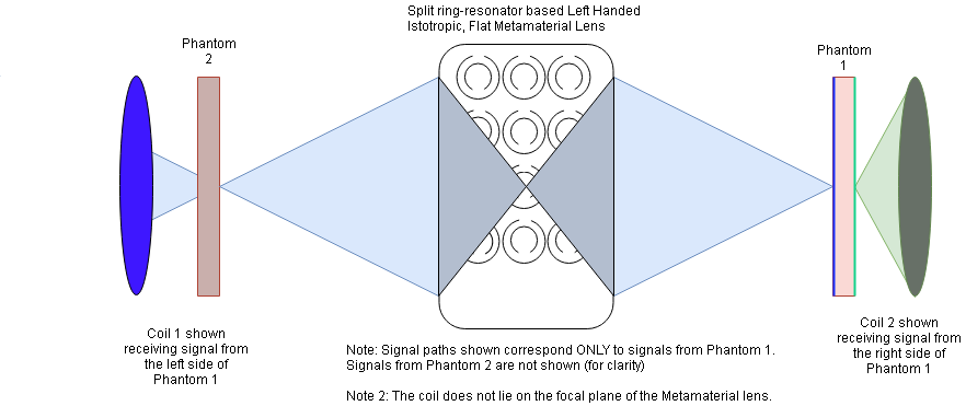
As shown in figure 1, coil-1 is receiving signal from the phantom-2 as it is close proximity to it, additionally it (coil-1) is receiving signal from phantom1 as it is under the focal or convergence area of the metamaterial lens. Same phenomena are applicable for coil-2 placed on opposite side.
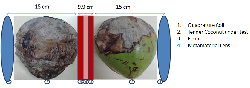
A 4-channel hexagonal shaped flex array is designed for 1.5T MR-scanner. This is then capacitive matched and balanced by an LC lattice 1:4 BALUN. Furthermore, geometrical overlapping is introduced to decouple them. The coils-balun assembly is further integrated with LNA and band pass filter. This receive chain was then tested against a standard transmit setup, comprising a circularly localized coil, connected to a Signal Generator supplying it with 63.87 MHz RF-sinusoid of -30 dBm, maintained at the same separation given in figure 3. Appropriate tuning was carried out in order to achieve these specifications. Once this was achieved, a flat, negative permeability metamaterial lens consisting of a periodic structure of split ring resonators, and tested at 63.87MHz; was incorporated in the imaging setup along with this receive chain. Two phantoms were placed adjacent to each other, with the metamaterial lens in between them. Next, the 4-channel hexagonal shaped flex array coils were wrapped with one each around the outer peripheries of each phantom. The distance between the phantom (a tender coconut) and the lens was set at 42mm, in order to ensure that the get better signal strength and to achieve convergence of signal at optimal distance. The metamaterial lens exhibits spatially symmetric operation.
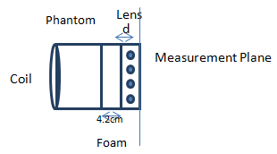
In Test setup of the experiment (Figure 2), an optimized distance between lens and coil is set to operate lens at its best resolving capability. The improvement in the system gain due to the Metamaterial lens was quantified using a double-probe based signal amplitude measurement on a vector network analyzer. The setup of the measurement is shown (Figure 2).
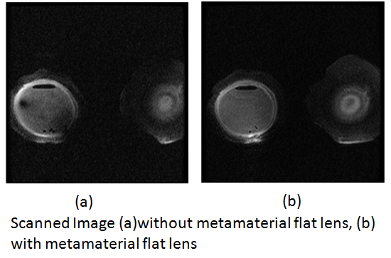
During imaging without the metamaterial lens, it was observed that the signal intensity from the portions of the phantoms that were proximal to the coil were much higher than the signal intensity from the portions of the phantom which lay distal to the coil plane. This led to a non-uniformity in the image, and would have necessitated either complex image processing, or complicated radiological interpretations to produce clinically useful images. With the placement of the metamaterial lens, however, the image uniformity is much better.
Results and Discussion
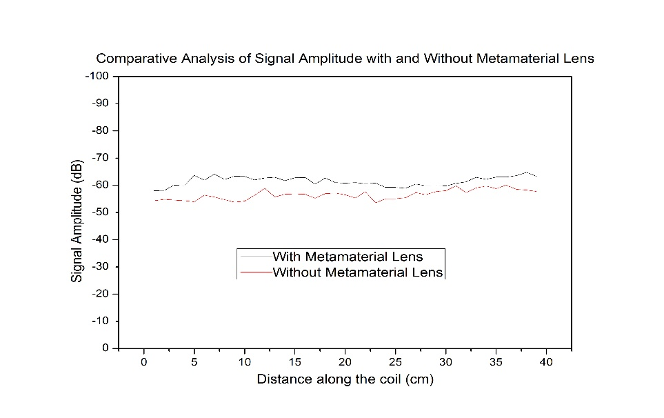
This experiment was conducted with double probe method using VNA. Signal amplitude is measured with and without lens and compared shown in figure (3). Improvement in signal amplitude is reported at 42 mm distance between lens and coil. in first case setup shown below arranged without flat lens inside the magnet. In second case a lens is placed between two phantoms, Analysis of image SNR between two cases proves improvement of SNR by 1.4 times of first case (Refer figure 3).Conclusion
A metamaterial lens was integrated into the receive chain of a 4-channel hexagonal shaped flex array coil: the objective being to increase the depth sensitivity of the receive channel, by converging the otherwise dissipative, divergent RF signals from the phantoms. It was observed that the received signal power improved by 4-5dB whereas the SNR of the image improved by the factor of 1.40(Figure 5). The scan parameters used were as follows: TE=20 TR=500, FOV=32cm X 32 cm Sequence=FRGE3* measured in 3-plane. Axial slices compared and SNR improvement seen 1.10times. The scan was performed on GE Signa Excite 1.5T MR Scanner at SAMEER, Mumbai.Acknowledgements
Authors are grateful to A. Sidhique, Dr. P. H. Rao for their support in this work.References
- D. H. Werner, C. R. Baleine, US Patent, 0002253, 2013
- M. J. Freire, R. Marques, L. Jelinek, Applied Physics Lett., 93:231108:1-3, 2008
- M. Vossen, W. Teeuwisse, M. Reijnierse, C. M. Collins, N. B. Smith, A. G. Webb, Journal of Magnetic Resonance, volume 208, Pages 291-297, 2011.
- Tejkiran A. Patil, A. Sidhique, Pulkit Sharma, Rajesh Harsh, P.H. Rao, Proc. Intl. Soc. Mag. Reson. Med. 26 (2018), 1707.
Figures