1552
Resonant and non-resonant coupled-wire coils for small-animal multinuclear imaging1Aix Marseille Univ, CNRS, Centrale Marseille, Institut Fresnel, Marseille, France, 2Aix Marseille Univ, CNRS, CRMBM- UMR 7339, Marseille, France, 3Department of Nanophotonics and Metamaterials, ITMO University, St. Petersburg, Russian Federation, 4Commissariat à l’Energie Atomique et aux Energies Alternatives, Direction de la recherche Fondamentale, NeuroSpin, Université Paris Saclay, Gif-sur-Yvette, France, 5ESPCI Paris, PSL Research University, CNRS, Institut Langevin, Paris, France, 6Institute of Theoretical Solid State Physics, Karlsruhe Institute of Technology, Karlsruhe, Germany, 7Institute of Nanotechnology, Karlsruhe Institute of Technology, Karlsruhe, Germany
Synopsis
Metasurface coils coupled with an unmatched loop were suggested earlier as an alternative to classical surface and volume coils, with the aim to optimize volume and sensitivity. We developed a new approach combining a commercial surface coil and a non-resonant coupled-wire structure. With this approach, the signal contribution from the driving loop can be efficiently added to that of the wire surface. The configuration was simulated, built and tested for 1H and 19F at 7T. The results showed that this new strategy improves the coil's sensitive volume while simultaneously maintaining high SNR.
Introduction
Commercial MR coils can be divided in two categories: volume and surface coils. Volume coils such as birdcage coils [1,2] offer large sensitive volume, but low SNR [3]. In contrast, surface coils present higher sensitivity, resulting in high SNR [4]. Tradeoff between large FOV and sensitivity has been targeted in earlier works on metamaterial RF coils coupled with a non-matched loop [5,6,7]. This configuration presented so far the best compromise between SNR and sensitive volume [7]. Nevertheless, a small surface coil [8] still provided the highest SNR. Therefore, the aim of this work was to investigate if advantages can be obtained by combining both strategies. We propose an elementary structure consisting of two parallel wires with adjustable length to switch between resonant and non-resonant regimes. We hypothesized that beyond their use in resonant regime, such structures can be used off-resonance and driven by commercial coils.Methods
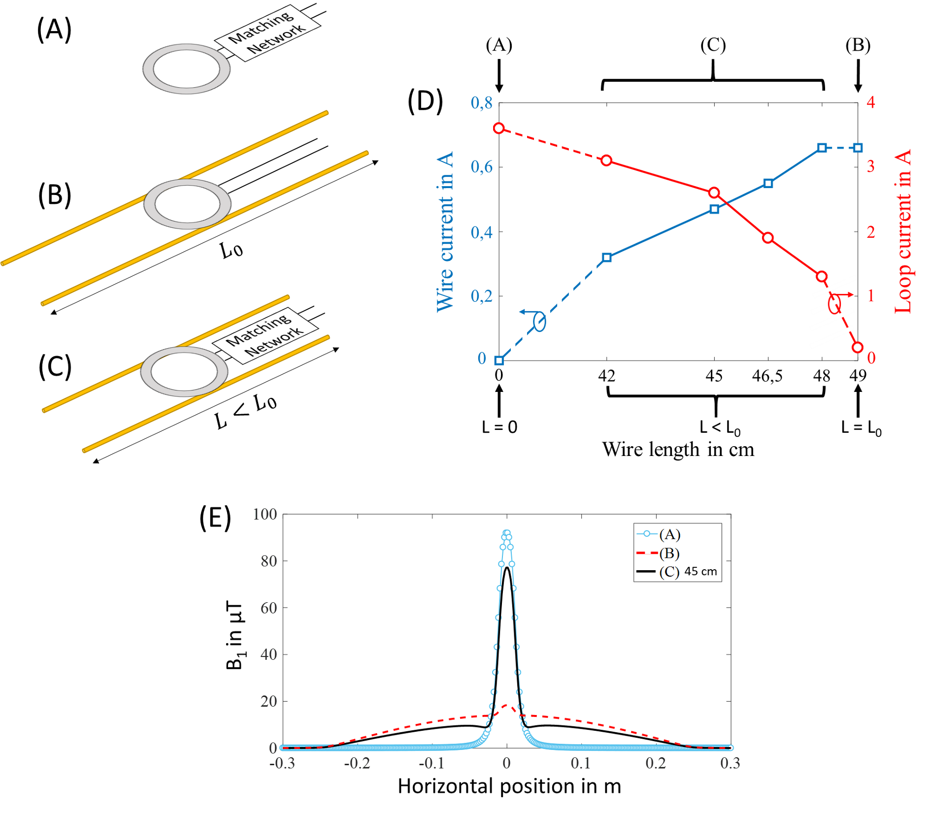
Three cases of coils were analyzed as single channel transmit-receive antenna for proton and fluorine imaging. Numerical simulations were carried out (Figure 1) to study the current distribution in the coils and their spatial B1 distribution. Case (a): surface coil (loop with a matched circuit), case (b): resonant coupled-wire coil (non-matched loop with two wires of length L0) and case (c): non-resonant coupled-wire coil (matched loop with two detuned wires of length L<L0) were simulated.
Prototypes of the simulated combinations of coils were built and tested for proton and fluorine with a phantom and in vivo using a Bruker PharmaScan 7T MR system. A commercial 1H birdcage coil was included in the experiments as additional reference for proton imaging.
Results
Figure 1D shows the maximum of the current amplitudes in the loop (red curve) and the coupled-wire structure (blue curve) in function of the wires length. Figure 1E shows the spatial B1 distribution on the horizontal axis. It can be seen that the highest B1 magnitude depends on the loop current while the enlargement of the sensitive volume depends on the wire current. Case (c) benefits from both contributions, resulting in a wide FOV and a high sensitivity.
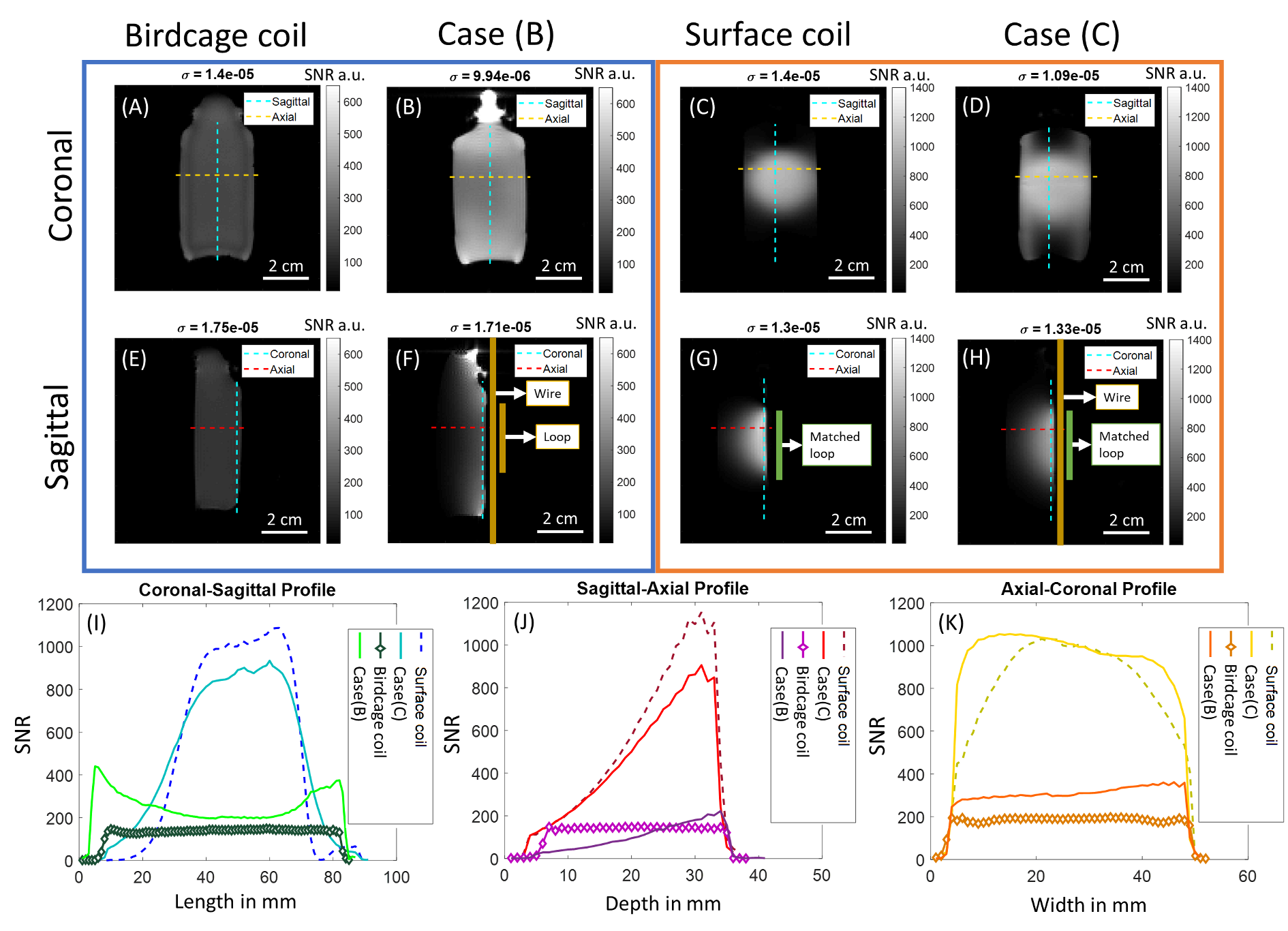
SNR maps and profiles of the phantom are shown in Figure 2. As expected from the numerical predictions, case (c), featured a notable enlargement of the sensitive volume compared to the surface coil alone (case (a)) while keeping a high SNR.
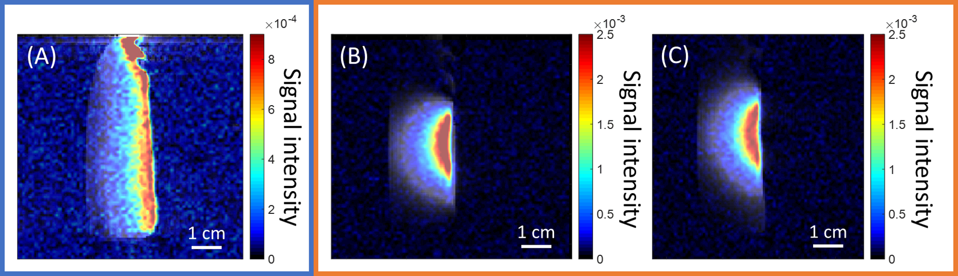
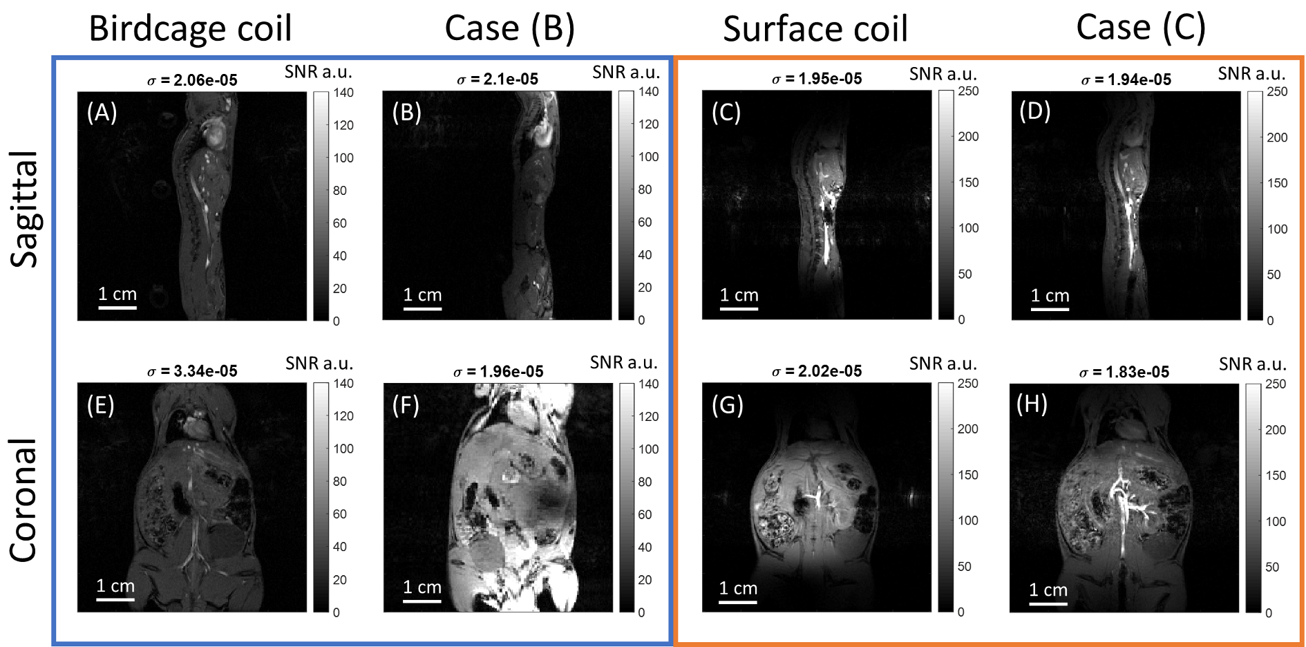
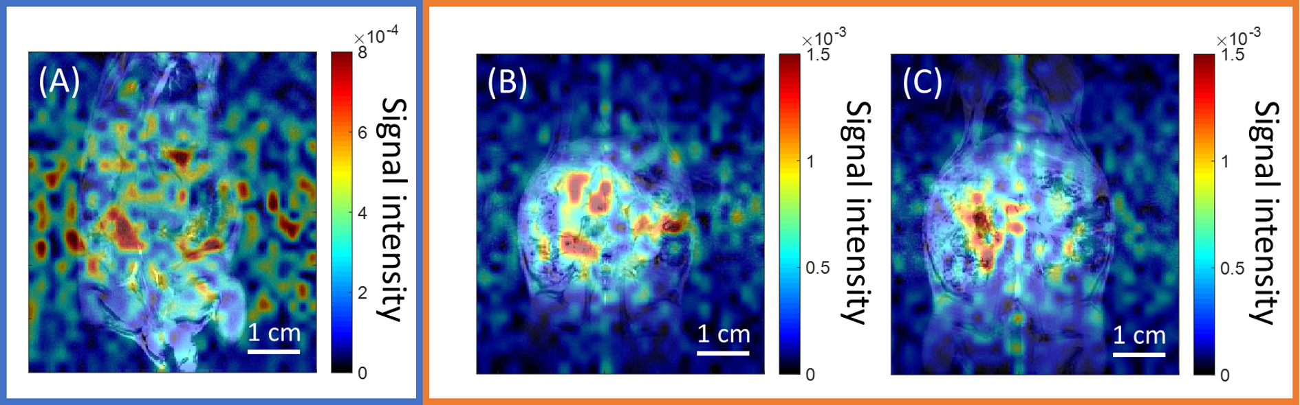
According to Figure 3, the coils showed a similar SNR distribution for fluorine as for proton. Figures 4 and 5 show the results of the in vivo experiments for 1H and 19F, respectively and proved that the behavior of the coils remained consistent in in vivo situations.
Discussion
The numerical studies show that when using a case (b) coil, the contribution of the loop is reduced due to the extremely low current flowing in it, resulting in a low B1. On the contrary, the current in the wires is almost constant, leading to a wide FOV.
Note that an attempt to benefit from both contributions by combining a matched loop with a resonant coupled-wire structure would be impeded by the strong mutual coupling [9]. To mitigate this and still benefit from both contributions we proposed a new approach combining a detuned coupled-wire structure with a surface coil (case (c)). This strategy allowed us to increase the loop current without strongly modifying the current within the wires, resulting in a coil with higher sensitivity and large FOV.
The simulation results were validated experimentally on a phantom and on mice in vivo imaging. The obtained results perfectly corroborate the numerical predictions from Figure 1. As expected, case (b) has a homogeneous but low SNR. Case (c) preserves the high SNR of the surface coil, but a significant enlargement of the sensitive volume can be clearly seen, particularly in vivo.
Conclusion
Coupled-wire structures can be used as RF coils in both resonant and non-resonant regimes. The chosen regime will affect the current amplitude distribution within the coil and therefore the spatial distribution of the B1 field. Experiments on phantom and in vivo confirmed the numerical predictions by coupling a carefully detuned coupled-wire structure with a commercial surface coil. It was further demonstrated that coupled-wire coils provide enough SNR to obtain 19F images at low concentrations. We believe that such structures bring a new and flexible alternative to the design of versatile RF coils, with the aim to mitigate the conventional trade-off between FOV and SNR.Acknowledgements
This project has received funding from the European Union’s Horizon 2020 research and innovation programme under grant agreement No 736937 and from the Ministry of Education and Science of the Russian Federation (project No. 14.587.21.0041 with the unique identifier RFMEFI58717X0041). The preclinical MRI scanner was acquired with help of the France Life Imaging National Programme - grant ANR-11-INBS-0006.References
[1] C. E. Hayes, W. A. Edelstein, J. F. Schenck, O. M. Mueller, M. Eash, Journal of Magnetic Resonance (1969) 1985, 63, 622–628.
[2] J. Tropp, Journal of Magnetic Resonance (1969) 1989, 82, 51–62.
[3] F. D. Doty, G. Entzminger, J. Kulkarni, K. Pamarthy, J. P. Staab, NMR in Biomedicine: An International Journal Devoted to the Development and Application of Magnetic Resonance In vivo 2007, 20, 304–325.
[4] J. Keltner, J. Carlson, M. Roos, S. Wong, T. Wong, T. Budinger, Magnetic resonance in medicine 1991, 22, 467–480.
[5] C. Jouvaud, R. Abdeddaim, B. Larrat, J. De Rosny, Applied Physics Letters 2016, 108, 023503.
[6] A. Hurshkainen, A. Nikulin, E. Georget, B. Larrat,D. Berrahou, A. L. Neves, P. Sabouroux, S. Enoch, I. Melchakova, P. Belov, et al., Scienti_c reports 2018, 8, 9190.
[7] M. Zubkov, A. A. Hurshkainen, E. A. Brui, S. B. Glybovski, M. V. Gulyaev, N. V. Anisimov, D. V. Volkov, Y. A. Pirogov, I. V. Melchakova, NMR in Biomedicine 2018, 31, e3952.
[8] Hoult D. The NMR receiver: a description and analysis of design. Progress in Nuclear Magnetic Resonance Spectroscopy 1978; 12(1):41–77.
[9] l Mispelter J, Lupu M, Briguet A. NMR probeheads for biophysical and biomedical experiments: theoretical principles & practical guidelines. Imperial College Press; 2006.
Figures