1543
Characterization of In-Bore 802.11ac Wi-Fi Performance1Electrical Engineering, Stanford University, Stanford, CA, United States, 2GE Healthcare, Aurora, OH, United States, 3Radiology, Stanford University, Stanford, CA, United States
Synopsis
In the context of flexible wireless coil arrays, characterization of achievable data rates is critical. This understanding will impact the types of scans whose data rates can be achieved in a wireless framework. The MR environment includes a cylindrical reflector as well as high power RF pulses, both of which may interfere with wireless communication inside the bore. By utilizing an embedded development platform, the relative impacts of the MR environment on Wi-Fi data rate were characterized and found to have little effect on the rate of data transfer.
Motivation
Wireless receive arrays have long been envisioned for MRI. To develop lightweight flexible, wirelessly powered wearable wireless array technology, it is vital to consider the achievable data rates within the bore. As a proof of concept, one may use existing Wi-Fi standards to wirelessly stream sampled k-space data back to a base station. Embedded development platforms have proved very popular for fast prototyping of electronic systems and are an attractive option for relaying information through a wireless link. To use one of these embedded platforms in a demonstration of a wireless MRI receiver, we must consider the potential effects of the MRI environment on the data rates one could achieve. Here we investigate the potential and limitations in employing the 802.11ac standard.Development Platform
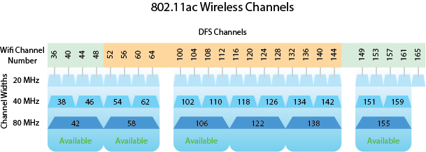
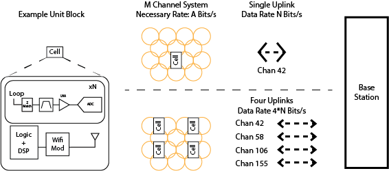
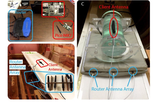
For feasibility tests, we used the Pico-Pi IMX7 embedded development platform, which supports 802.11ac wireless standards with a CYW4339. Within the MRI bore, much of the adjacent channel interference common to Wi-Fi is not present and one should be able to choose the desired Wi-Fi channel free of concern. The available channels are shown in [Figure.2]. To achieve the highest possible data rate, one should operate with an 80MHz channel width. Within the 802.11ac standard, there are six available 80 MHz channels, but four of these are dynamic frequency selection bands (DFS) which must be vacated if radar signals are detected. We used a Linksys WRT3200ACM which supports DFS bands. Within a mock bore environment [Figure.4B], the Pico-Pi development platform was able to connect to four of the possible six. This infers that one could potentially have four wireless links working in tandem in each of those four channels. Each of those four devices could manage one ’cell’ of MRI coils and relay their output to the base station receiver as depicted in [Figure.3]Effects of the MR Environment
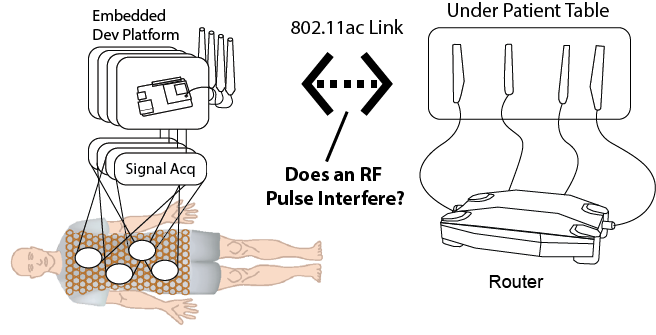
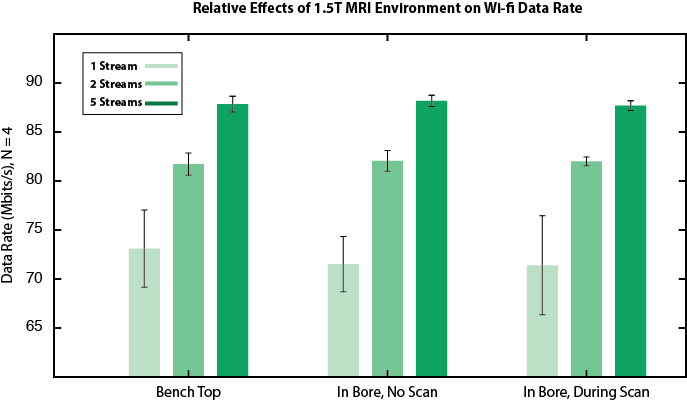
The MRI environment presents a unique wireless channel for two main factors. First, its structure acts as reflector and this could potentially cause destructive interference and decrease channel SNR. In addition, the high-power RF pulses emitted by MRI, though at a significantly different frequency, could interfere, causing signal blocking in the Wi-Fi receive chain. To examine these effects, extension cables were attached to the antennas of the Pico-Pi IMX7 development platform as well as the WRT3200 router, used as a base station. The linux networking utility iperf characterized the uplink rate of the client pico-pi device to the server, a laptop connected to the router via gigabit ethernet. Uplink rate is most representative since MRI data must ultimately be streamed from on-coil electronics to a router. TCP packet window size was made large enough such that the handshake protocol did not significantly impact achievable data rates. The number of parallel iperf connections were also swept from one to five to achieve best performance. Once a baseline rate was established in a benchtop environment [Figure.4A], the router and embedded platform were moved to the MRI environment. The embedded device and router were far enough such that the magnetic field did not saturate the power supplies of the devices, interrupting their operation. From these devices, SMA cables were fed to the patient table. The three antennas of the base station router were placed under the cushion of the patient table and the client antenna was placed on top of a phantom [Figure.4C]. Inside the MRI bore, iperf throughput tests were repeated, first without MRI scanning. Throughput rates reached 90 Mbps, similar to the mock bore outcome. The iperf test was then repeated while playing a gradient echo sequence, (TR 7ms, 5 minutes duration, 30 degree flip angle), and yielded similar throughput. Results for all three tests for an N of four are shown in [Figure.5].Discussion
In the MRI environment, bore reflection and RF pulse power had an imperceptible effect on the data uplink rate of the client device to the server. This bodes well for 802.11ac wireless platforms to relay sampled data to a base station for reconstruction. However, uplink rates of 87 Mbps do fall short of the expected 270 Mbps that a single stream 80 MHz channel can attain. The Wi-Fi SDIO interface is a suspected data bottleneck. For reference, a 3D cones high speed sequence with 32 Coils, +/-250 kHz BW, 3.84ms TR and 936us Tacq will generate 156 Mbps if data is decimated to 500 ksps and 20 bit I/Q. More coils, less decimation or higher gradient bandwidths could easily multiply data bandwidths. The 802.11ac standard appears capable of handling MRI data rates, but capacity is limited.Acknowledgements
We would like to thank GE Healthcare for their research support. This project is supported by NIH grant R01EB019241References
Byron K, Robb F, Stang P, Vasanawala S, Pauly J, Scott G. An RF‐gated wireless power transfer system for wireless MRI receive arrays. Concepts Magn Reson Part B. 2017;47B:e21360. https://doi.org/10.1002/cmr.b.21360
Corea, J. R. et al. Screen-printed flexible magnetic resonance imaging receive coils. Nat. Commun. 7:10839 doi: 10.1038/ncomms10839 (2016).
Figures