1541
Simulations of Integrated Radio-Frequency/Wireless Coil Designs for Simultaneous MR Image Acquisition and Wireless Communication1Medical Physics, Duke University, Durham, NC, United States, 2Brain Imaging and Analysis Center, Duke University, Durham, NC, United States
Synopsis
A novel RF coil design, termed an RF/wireless coil, enables simultaneous image acquisition and wireless communication by allowing currents to flow simultaneously at the Larmor and WIFI frequencies. Measurements of the far-field radiation parameters are not practical in an MRI scanner. Thus, simulations are performed to optimize the far-field performance within the scanner bore to maintain the wirelessly transmitted data integrity. In this work, finite element simulations, verified with anechoic chamber gain-pattern measurements and SNR maps from a constructed RF/Wireless coil, are performed to optimize the far-field gain, directivity, and link budget of the RF/Wireless coil within the scanner bore.
Introduction
The data transfer among different MRI scanner subsystems (e.g., RF coils, shim coils, console outside the scanner room) currently takes place through a complex network of wired connections, which requires careful routing and costly RF components to maintain the image quality and data integrity. To reduce the number of wired connections, we recently proposed a novel integrated RF/wireless coil design, which allows RF currents both at the Larmor frequency and in a wireless communication band to flow on the same coil for simultaneous RF signal reception and wireless data transfer1,2. As a first application, this design was combined with the integrated RF/shim (iPRES) coil design3 and shown to be able to simultaneously perform image acquisition and wirelessly control DC currents for localized B0 shimming with no degradation in SNR during wireless data transmission2,4. RF/wireless coils could also be used to wirelessly transfer image data from within the scanner bore to one or more access point(s) (AP) in the scanner room that relay the data to the console. The integrity of the data transmitted from the coil to the AP is directly related to the amount of radiated power coupled between them (link budget). Large losses in the link budget are possible when the coil is placed close to a subject within the scanner bore. In this work, proof-of-concept simulations of an RF/wireless coil design were performed to determine the optimal location of the coil on a head phantom that maximizes its gain, directivity, and link budget outside the bore. These simulations were compared to SNR measurements on a 3T scanner and far-field measurements in an anechoic chamber.Methods
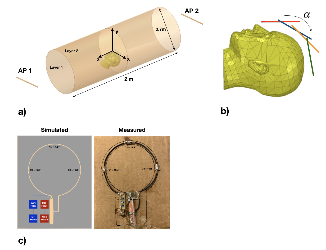
A 7-cm diameter RF/wireless coil was modeled on a head phantom (ANSYS HFSS 19.0) with three identical lumped port capacitors and two RF sources at 127.7 MHz (MRI port) and 2.442 GHz (WIFI port) to produce the B1 magnetic field and far-field radiation for simultaneous imaging and wireless communication. The two ports were isolated from each other (S21 < -35 dB) by inserting high-impedance band-stop filters at 2.442 GHz and 127.7 MHz between the coil and the MRI or WIFI ports, respectively. Next, a scanner bore was modeled as a 70-cm diameter cylindrical two-layer impedance boundary, with the interior and exterior layers assigned to be 5-cm FR4 epoxy substrates and perfect electric conductors to represent lossy and reflective materials in the scanner. Finally, two 2.4-GHz dipole antennas, representing two APs in the scanner room, were added outside the scanner bore to allow the link budget between the coil and each of them to be simulated (Fig. 1a). First, a hybrid finite element and integral equation simulation was performed with the coil, but no bore or phantom in the model, to determine the baseline SNR and radiated performance (e.g., 3D and principal plane gain patterns) of the design. Next, after the bore and phantom were added to the model, simulations were performed with the coil at four separate positions (𝝰 = 0o, 30o, 45o, 80o) on the head to determine the optimal link budget between the coil and the each of the dipoles (Fig. 1b). Lastly, to verify the simulations, an RF/wireless coil was constructed, tuned on a 4-port vector network analyzer (Fig. 1c), and used to acquire an SNR map of a water phantom on a 3T scanner and a free-space radiation pattern measurement in a 3x2x2 m calibrated anechoic chamber.Results
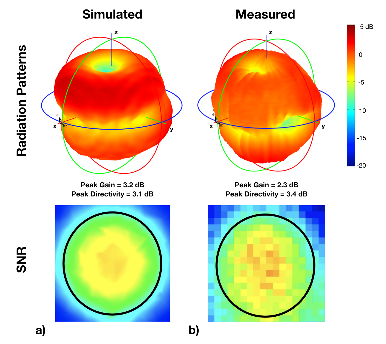
Figure 2 shows that the simulated and measured SNR maps and far-field radiation patterns were similar and that the corresponding peak gain and directivity only differed by 0.9 and 0.3 dB, respectively.
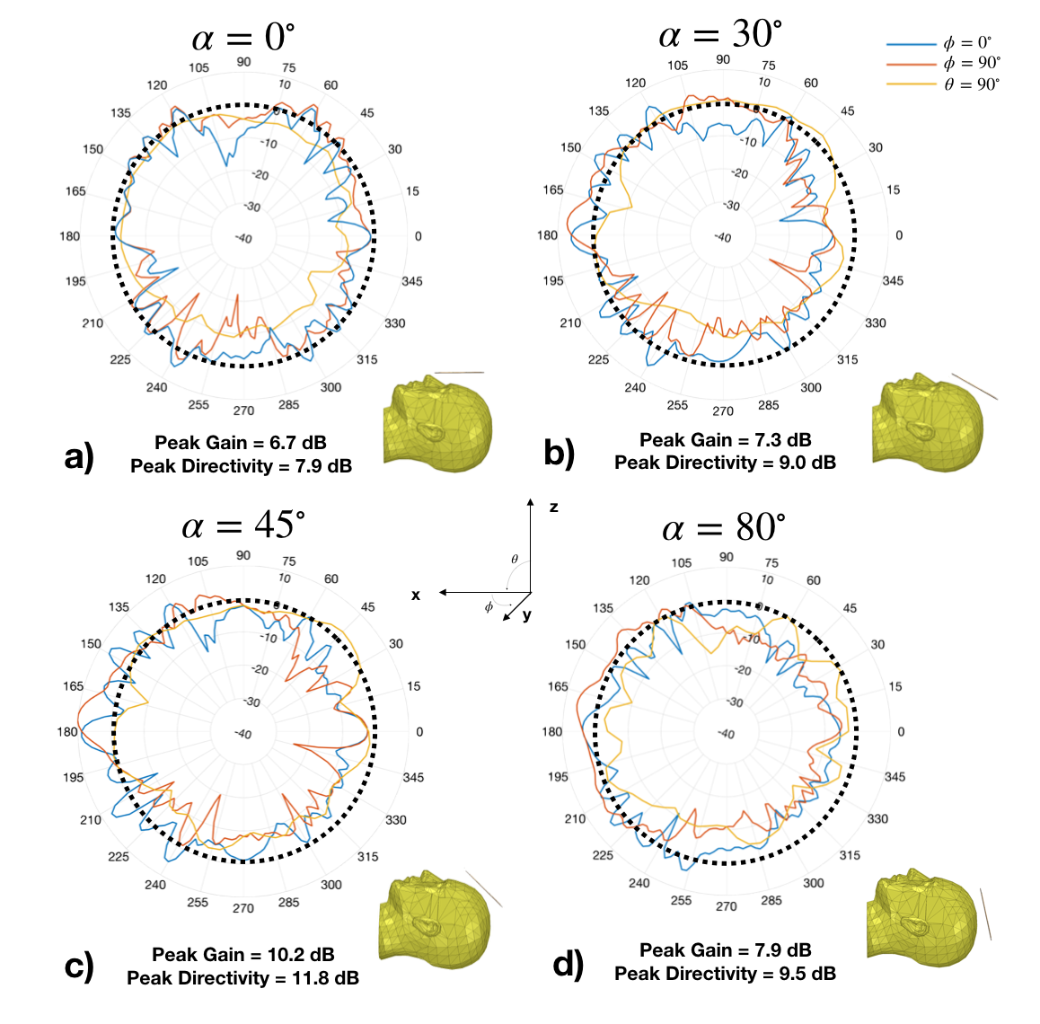
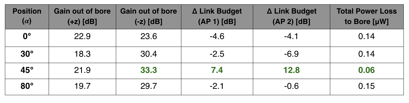
Figure 3 shows that the gain and directivity were maximized with the coil at 𝝰 = 45o (Fig. 3c). The link budget between the coil in this position and the dipoles at the front and back of the scanner improved by 7.4 and 12.8 dB, respectively. Further, the gain through the solid angle subtended from each end of the scanner bore (gain ± z) was maximized and the total power loss to the bore was minimized with the coil in this position (Table 1).
Discussion and Conclusion
These proof-of-concept simulations and measurements demonstrate that the far-field gain and directivity of an RF/wireless coil can be optimized by changing the position of the coil in the scanner bore to maximize the link budget for data transfer. Such a numerical optimization will facilitate the development and improve the performance of future RF/wireless coil arrays, which will enable the wireless transfer of image data from the scanner bore.Acknowledgements
This work was in part supported by grants R21 EB024121, R01 NS075017, and S10 OD 021480 from the National Institutes of Health, by GE Healthcare, and by the Duke-Coulter Translational Partnership. We thank Rob Schlub for his generous support with the anechoic chamber.References
- Darnell D et al. Proc. ISMRM 2017; 25:4430
- Darnell D et al. Mag. Reson. Med. 2018. doi: 10.1002/mrm.27513
- Truong TK et al. NeuroImage 2014; 103;235-40
- Cuthbertson J et al. Proc. ISMRM 2018; 26:0016
Figures