1540
Ultra-Flexible Electro-Textile 4-Channel MRI RF Coil Array for Neck MRI1Electrical and Computer Engineering, University of California, Los Angeles, Los Angeles, CA, United States, 2Radiological Sciences, University of California, Los Angeles, Los Angeles, CA, United States
Synopsis
Current surface coils used for neck MRI are either uncomfortable for patients to wear or suffer from low Signal-to-Noise Ratio (SNR).
Introduction
Many anatomical regions have complex curvatures difficult for surface RF coils to be positioned. The neck, for example, has abrupt and irregular shape changes both at and around the areas between the head and neck. The limited flexibility of the conductive and dielectric material used by current RF coils makes it challenging to achieve ergonomic fit and high SNR. Flexible receive coils have two major advantages: (1) more ergonomic and versatile coverage for different patient sizes, shapes and regions of anatomy, (2) improved Signal-to-Noise Ratio (SNR) and image quality for specific applications. In this work, electro-textile (e-textile) material with flexibility close to cotton cloth was used to design a new ultra-flexible 4-channel RF receive coil array for neck MRI.
Methods
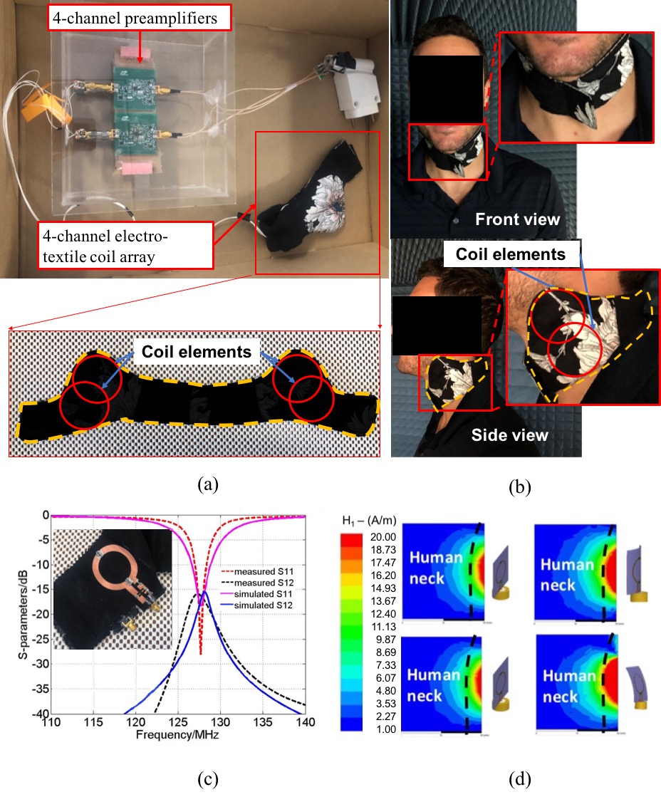
E-textile characterization and coil design: We used a conductive cloth with superb conductivity at 123 MHz (3 Tesla). The design process involves four major steps(1). First, the e-textile effective conductivity of S/m at 123 MHz was found using a four-microstrip-line measurement method(2), where the conductive cloth surface roughness was considered. Second, High Frequency Electromagnetic Field Simulation Software (HFSS) was used incorporating the effective conductivity found in first step. Third, coil pattern based on the design in second step was fabricated using computerized laser cutting facility (Epilog Laser Helix) and was attached to cotton cloth using adhesive materials. The electrical components were soldered onto the pattern with controlled temperature. Finally, the coil elements were fine-tuned near a saline water phantom ($$$\sigma=1.109 S/m$$$). The coil element diameter was 5 cm to target the neck tissues. The 4-channel RF array coil was designed and optimized with two overlapped elements on each side of the neck (Fig. 1a). It comfortably and closely wraps around the patient’s neck (Fig. 1b). PIN diodes were used to detune the coil during the RF transmission phase. The preamplifier (TI TL5500) was noise-matched to achieve 0.5 dB Noise Figure (NF) and 28.5 dB gain(3).
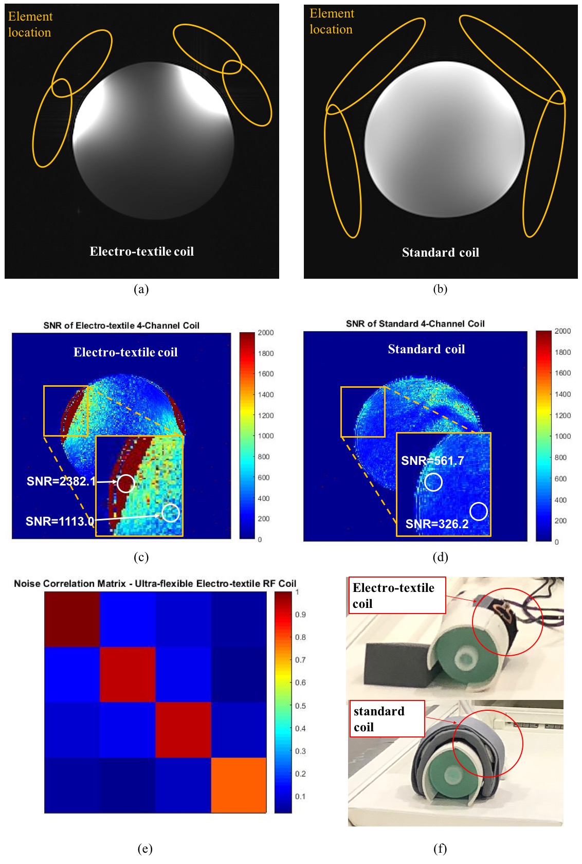
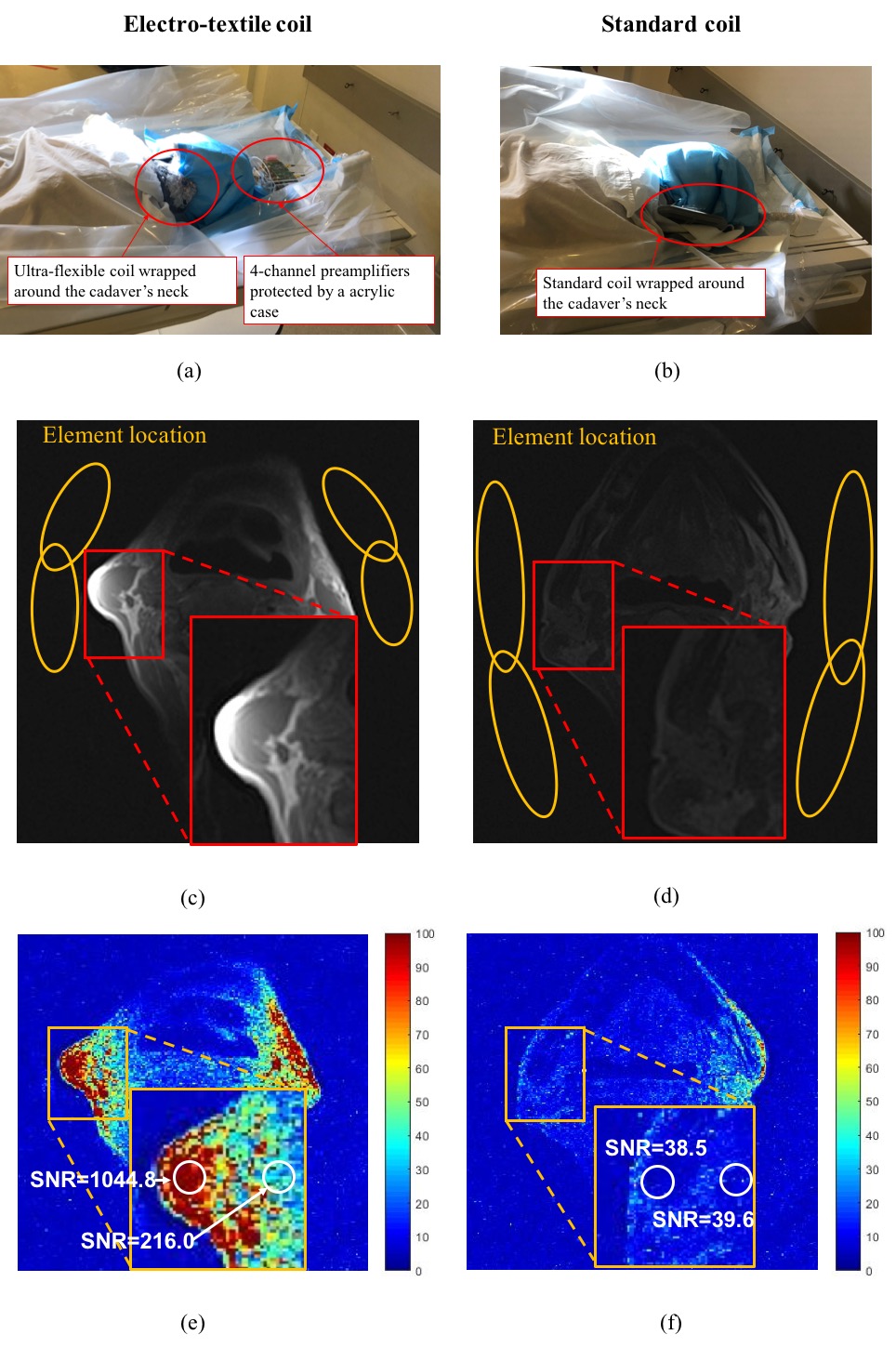
MRI experiments: The ultra-flexible e-textile coil and a 4-channel standard surface coil (small flex coil, Siemens) were used to scan a water phantom (Fig. 2f) and the neck of an unembalmed cadaver at room temperature at 3T (Prisma, Siemens) (Fig. 3a, b). Biosafety approval was obtained for human cadaver research. The coil locations are indicated by the yellow ellipses. A T1-weighted spin-echo sequence was used for both phantom and cadaver, with 1$$$\times$$$1 mm2 in-plane resolution, 0.8 mm slice thickness, and FOV=320$$$\times$$$320 mm2. For phantom scans: TR=573 ms, TE=20 ms. For cadaver scans: TR=309 ms, TE=11 ms.
Results
Simulation and bench testing: Satisfactory impedance matching was achieved at 123 MHz (Fig. 1c). The measured S21<-15 dB between all coil elements, showing low mutual coupling. The simulated H1- field (Fig. 1d) shows a deeper penetration depth in HFSS when it is conformal to the cylinder with a 10 cm-diameter.
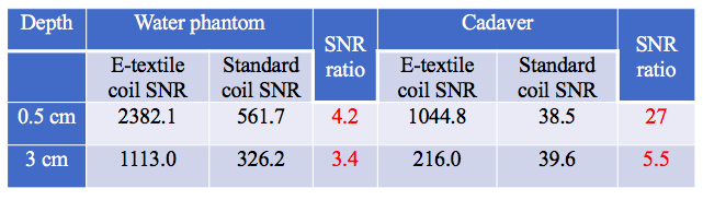
Phantom imaging: The signal strength of e-textile coil near the surface is noticeably stronger than a standard surface coil (Fig. 2a, b). The SNR calculated using the difference method(4) at the depths of 0.5 cm and 3 cm were 4.2 and 3.4 times (Table 1) higher than the standard coil respectively at the indicated ROI (Fig. 2c, d). The noise correlation matrix shows that the minimum on-diagonal value is 77.6% of the maximum. The off-diagonal maximum is 13.4% of the on-diagonal maximum (Fig. 2 e), indicating satisfactory coil array performance(5).
Human cadaver imaging: The signal strength near the surface is noticeably stronger than a standard surface coil (Fig. 3c, d). The SNR calculated using the difference method(4) at the depths of 0.5 cm and 3 cm was 27 and 5.5 times (Table 1) higher than the standard coil respectively at the indicated ROI (Fig. 3e, f). An expert radiologist reported good depiction of vertebral artery and sternocleidomastoid muscle in the images.
Discussion
The new ultra-flexible electro-textile RF array coil shows substantial SNR advantage over a standard coil. The SNR in cadaver images at a depth of 0.5 cm from the coil was one order of magnitude higher than a standard coil. The cadaver images showed high-quality anatomical features in the neck. As the size and number of coil elements can be modified for different anatomies of interest, this technology is not limited to neck MRI. The electro-textile material can be readily applied to more areas including pediatric, joint, and extremity MRI, and MRI-guided interventions. Future work includes the in-vivo evaluation of the new coil for different diagnostic applications.Conclusion
An ultra-flexible electro-textile RF array coil was designed and tested to show its ergonomic benefit and substantial SNR advantage over a standard coil in neck MRI.Acknowledgements
The authors would like to thank the UCLA Donated Body Program for assisting the research scans.References
(1) D. Zhang and Y. Rahmat-Samii, Integration of Electro-textile RF coil Array with Magnetic Resonance Imaging (MRI) System: Design Strategies and Characterization Methods, International Workshop on Antenna Technology (iWAT), Mar. 5th, 2018
(2) D. Zhang and Y. Rahmat-Samii, A Novel Flexible Electro-textile 3T MRI RF Coil Array for Stroke Prevention: Design, Characterization and Prototyping, IEEE Transactions on Antennas and Propagation, Special issue Wireless Healthcare Biotechnology, Nov. 2018
(3) P. Roemer et al., The NMR phased array, MRM 1990 Nov;16(2):192-225
(4) Dietrich O, et al., Measurement of signal-to-noise ratios in MR images: influence of multichannel coils, parallel imaging, and reconstruction filters. J Magn Reson Imaging 2007;26:375-385
(5) E. M. Tunnicliffe et al., Use of the noise covariance matrix in array coil quality assurance, ISMRM 2011; 19; 4548-4548
Figures