1539
About the MRI compatibility of fuel cells as the power source for PET detectors1Department of Physics of Molecular Imaging Systems, Institute for Experimental Molecular Imaging, RWTH Aachen University, Aachen, Germany, 2Philips Research Europe, Eindhoven, Netherlands, 3Chair for Fuel Cells, RWTH Aachen University, Aachen, Germany, 4Institute of Energy and Climate Research, IEK-3: Electrochemical Process Engineering, Forschungszentrum Jülich GmbH, Jülich, Germany
Synopsis
Since MRI is very sensitive regarding electromagnetic disturbances, the integration of a Positron Emission Tomography (PET) detector into in an MRI system is a sophisticated task. The power supply and cabling of the PET detectors are the main sources of electromagnetic interferences with the MRI. Therefore, we propose to power the PET detectors with a proton-exchange membrane fuel cell (PEMFC). To prove the feasibility of the concept, we evaluated the MRI compatibility of the PEMFC. The PEMFC was able to power PET detectors and only a minor influence of the PEMFC on the B0 homogeneity and noise level was measured.
INTRODUCTION
Hybrid Magnetic Resonance Imaging (MRI) and Positron Emission Tomography (PET) systems combine high soft-tissue contrasts and functional information. Since MRI is very sensitive regarding electromagnetic disturbances, the integration of a PET detector into in an MRI system is a sophisticated task. Besides the bias voltage for the photon detecting diodes, the PET electronics are powered with low voltages and high amperage. For this purpose, inflexible and expensive cables are needed to mitigate heat dissipation and voltage drop. Furthermore, power supply and cabling are the main sources of electromagnetic interferences with the MRI. Therefore, we propose to power the PET detector with a proton-exchange membrane fuel cell (PEMFC) in the MRI bore. This eliminates galvanic cabling to the power supply, enables electrically floating PET detectors [1], and thus, increases the MRI compatibility.METHODS
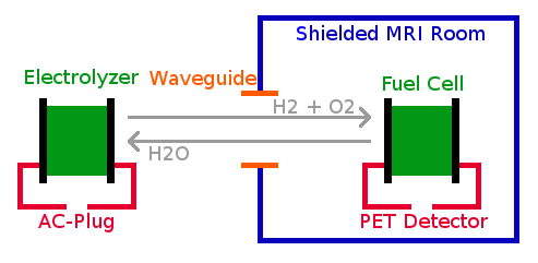
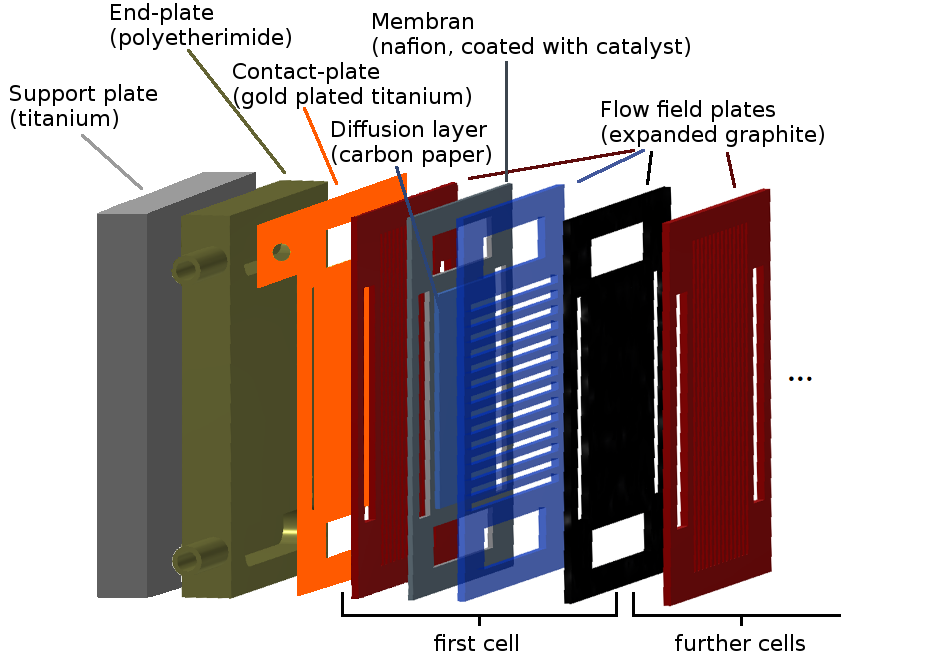
A sketch of the concept is depicted in figure 1. The electrolyzer outside the MRI room provides H2 and O2 for the PEMFC which is placed inside the MRI bore close to the PET detector. To test the feasibility of the concept, the PEMFC was designed to power one singles detection module (SDM) of the Hyperion IID PET insert [2]. The SDM consumes about 30 W with three different voltage ranges: PS-High ((4.1 - 5.2) V), PS-Mid ((2.5 - 5.2) V) and the bias voltage ((30 - 42) V). PS-High and PS-Mid consume (3 - 4) A, whereas the bias voltage only needs (10 - 20) mA. We aim to power PS-High and PS-Mid with the PEMFC since the above discussed problems do not apply for the low current bias voltage and it is rather difficult to produce the high voltage with a PEMFC. Figure 2 shows a sketch of the PEMFC, which is based solely on non-ferromagentic materials. To test effect of the strong static magnetic field B0, the PEMFC was slowly moved inside the 3-T MRI in all three orientations perpendicular to the B0 field. The influence of the gradient magnetic fields was tested by placing the PEMFC at 30 cm offcenter in z-direction and switching rectangular gradient fields with a strength of 30 mT/m, a slew rate of 200 mT/m/ms and a plateau time of 1 ms during 15 s [3]. For all measurements, the PEMFC was connected to a load and we monitored the produced voltage. Furthermore, we measured the amount of noise emitted by the PEMFC which coupled into the MRI body coil as well as a B0 map to evaluate the effect of the fuel cell on the B0 field homogeneity.RESULTS & DISCUSSION
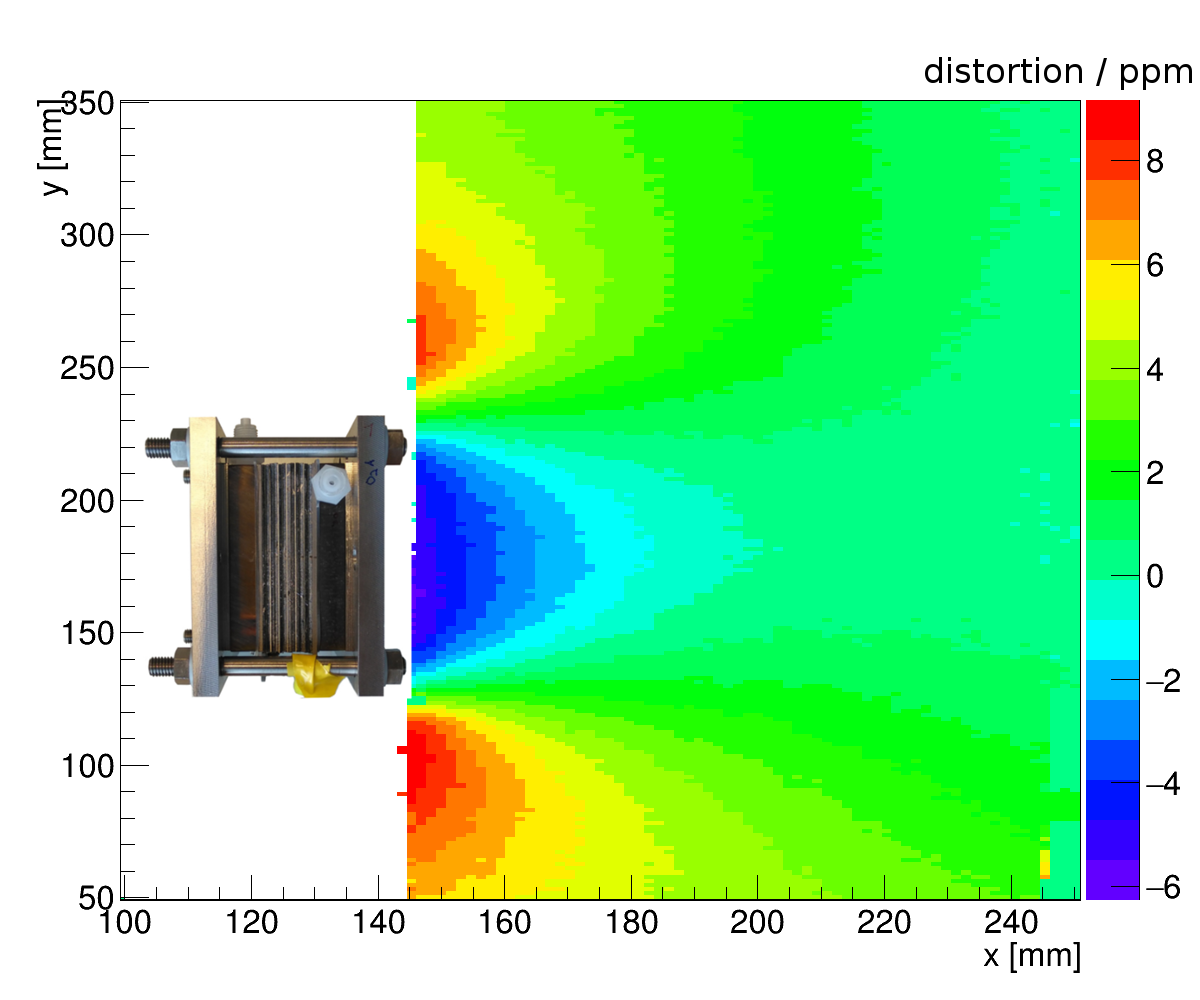
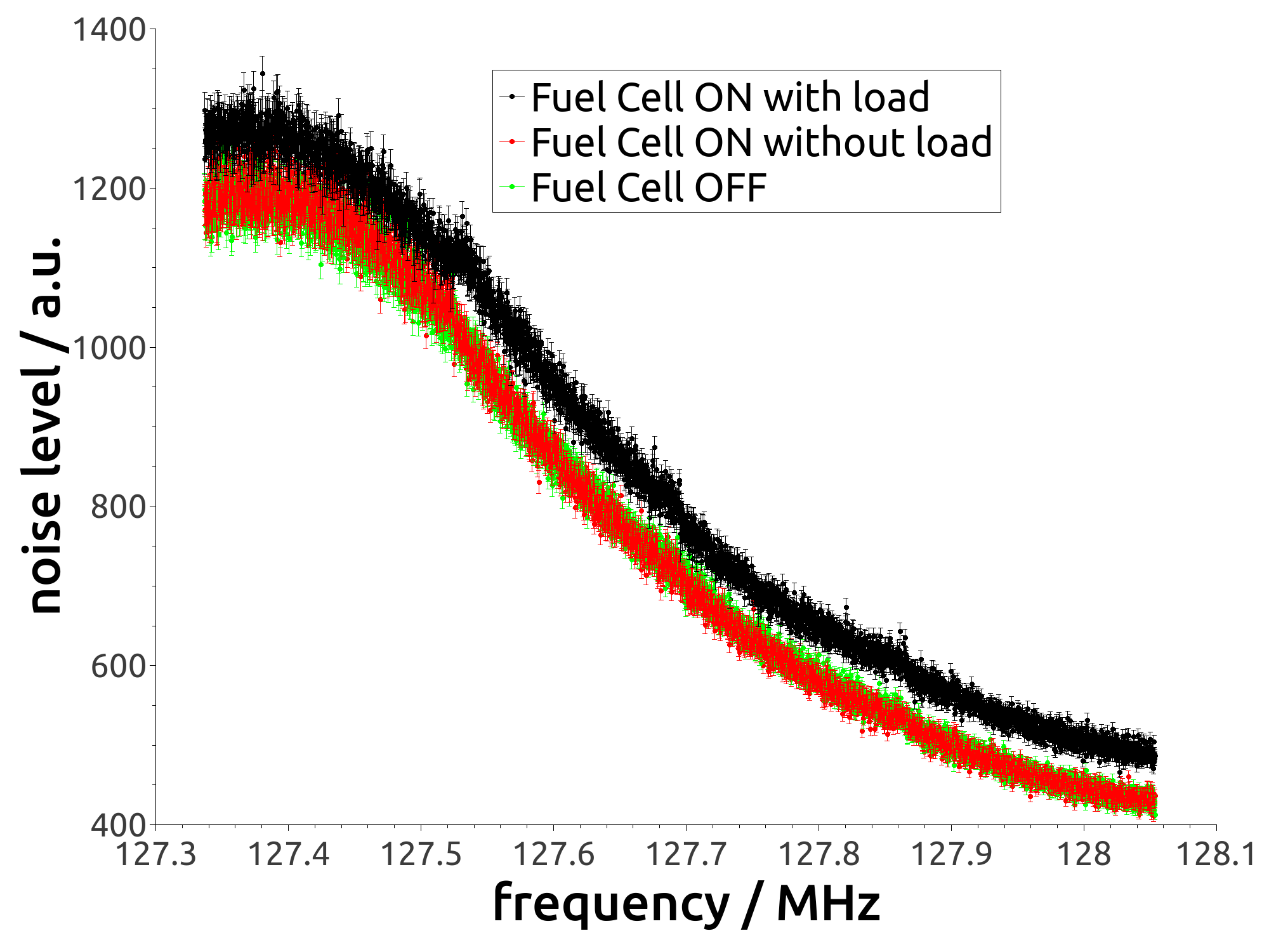
We observed no effect on the produced voltage while moving or operating the PEMFC inside the B0 field. During gradient switching, we measured a slight fluctuation of the voltage which remained below 0.1 V. Since the possible operating voltage of the PET detectors is rather flexible due to voltage regulators, these fluctuations are harmless. The B0 map is presented in figure 3. Close to the PEMFC, the B0 field is strongly disturbed because of the rather high susceptibility of the titanium and graphite. However, the distortion drops below 1 ppm in about 4 cm distance from the PEMFC. The noise scan of the body coil is shown in figure 4. A very slight increase in noise is visible for the measurement with the operating PEMFC connected to a load. To eliminate the noise, it would be possible to implement the PEMFC in an radio-frequency shield, such as the PET detectors. This would also prevent that higher voltages are induced by the radio-frequency pulses of the MRI system on the power line.CONCLUSION & OUTLOOK
We designed a PEMFC to power PET detectors inside the MRI bore. MRI compatibility tests showed only a minor influence of the PEMFC on noise level and B0 homogeneity. Thus, the concept was proven to be feasible. To further reduce the noise, the PEMFC is planed to be shielded. Furthermore, we plan to reduce the size of the titanium plates, which would improve B0 homogeneity.Acknowledgements
This project has received funding from the European Union's Horizon 2020 research and innovation programme under grant agreement No 667211.References
[1] Lee, Brian J., et al. "MR performance in the presence of a radio frequency-penetrable positron emission tomography (PET) insert for simultaneous PET/MRI." IEEE Transactions on Medical Imaging (2018).
[2] Weissler, Bjoern, et al. "A Digital Preclinical PET/MRI Insert and Initial Results." IEEE Trans. Med. Imaging 34.11 (2015): 2258-2270.
[3] Wehner, Jakob, et al. "MR-compatibility assessment of the first preclinical PET-MRI insert equipped with digital silicon photomultipliers." Physics in Medicine & Biology 60.6 (2015): 2231.
Figures