1535
Harvesting Power Wirelessly from MRI Scanners1Electrical Engineering, Stanford University, Stanford, CA, United States, 2GE Healthcare, Aurora, OH, United States, 3Radiology, Stanford University, Stanford, CA, United States
Synopsis
As the number of devices accompanying patients inside the MRI bore increases, so does the need for reliable powering inside the MRI. The high-power B1 field in MRI suggests the capability to harvest power wirelessly from the scanner itself. With high quality factor coils and a high efficiency class-E rectifier we are able to harvest 100s of µJ /TR. However, B1 harvesting will generate flip angle banding when harvesting loops are near imaging regions. These banding artifacts increase with increasing coil size and decrease with larger coil loading.
Introduction
Additional on-patient monitoring devices are becoming more common in the MRI bore with a need to power these devices. Non-magnetic batteries have limited power levels and must maintain a high charge. The high-power B1 field in MRI suggests the capability to harvest power wirelessly from the scanner itself. This concept was shown in 1, where almost 10 µJ of energy/TR was harvested to power a VCO. Here, we examine how to make an efficient energy harvester, delivering 100s of µJ of energy/TR to a resistor load. Efficient energy harvesting requires careful attention to coil design, rectifier design and both patient and resistor loading. The power harvester design is also limited by requirements for MRI compatibility, such as coil size and flip angle distortion relative to the desired imaging region.Methods
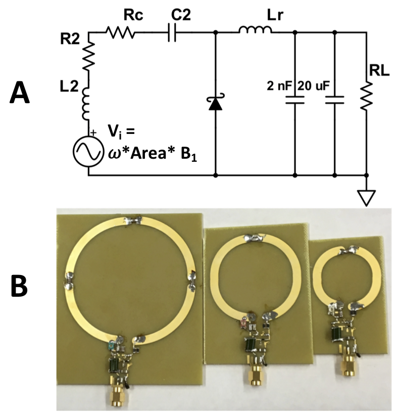
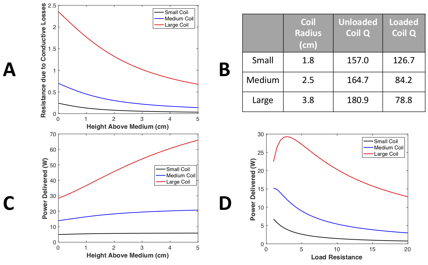
Typical wireless power transfer (WPT) systems2 use resonant inductively coupled coils to transfer and receive power at a particular frequency. This is modeled as a two-port network, with efficiency dependent on the coil coupling and quality factors (Q), as well as the load impedance. For small harvesting coils, the mutual inductance to the MRI whole-body coil is quite low. Hence, Faraday’s law alone determines the voltage induced on a resonant harvesting coil (Figure 1A) and is dependent on the field strength, frequency, and size of the harvesting coil. A perfectly resonant coil then acts as a voltage divider between the parasitic resistance and the load impedance. The proximity to the patient will cause additional parasitic loading losses on the harvesting coil, modeled by Suits3 load equations. For three harvesting coils (Figure 1B), induced conductivity losses are shown versus distance from the conductive (𝜎 = 0.5 S/m) medium in Figure 2A. Figure 2B shows the measured unloaded and loaded Q of each coil, with conductive loading having the greatest effect on the largest coil, as expected. Disregarding rectifier losses and assuming peak B1 of 10 µT, peak power, delivered to a 2 Ω load, increases with patient separation for the largest coil. At fixed distance from the conductive surface (0cm), an optimal load resistance maximizes power delivery (Fig. 2D). For the simple series-resonant matching network, this optimal load equals the parasitic resistance of the coil plus induced conductive loss. Figure 1A shows the complete harvesting circuit, which includes a class-E resonant rectifier for RF-to-DC power conversion. This rectifier is designed based on equations in [4], with the diode parasitic capacitance resonated out at the MRI frequency by inductor Lr to improve rectifier efficiency. At 1.5T, the MRI frequency is sufficiently high that no additional capacitance is needed across the diode.Results
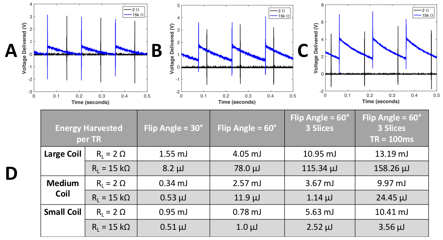
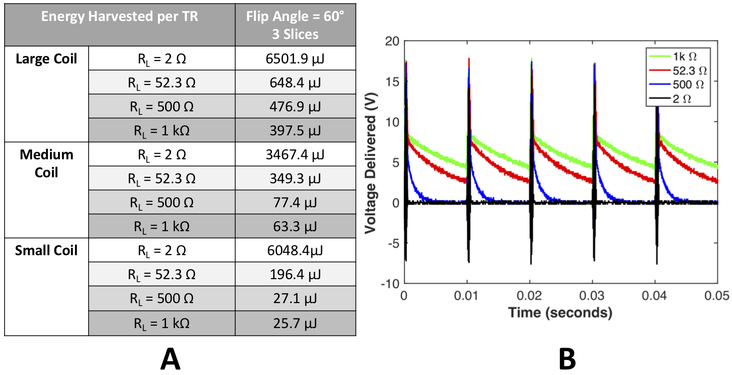
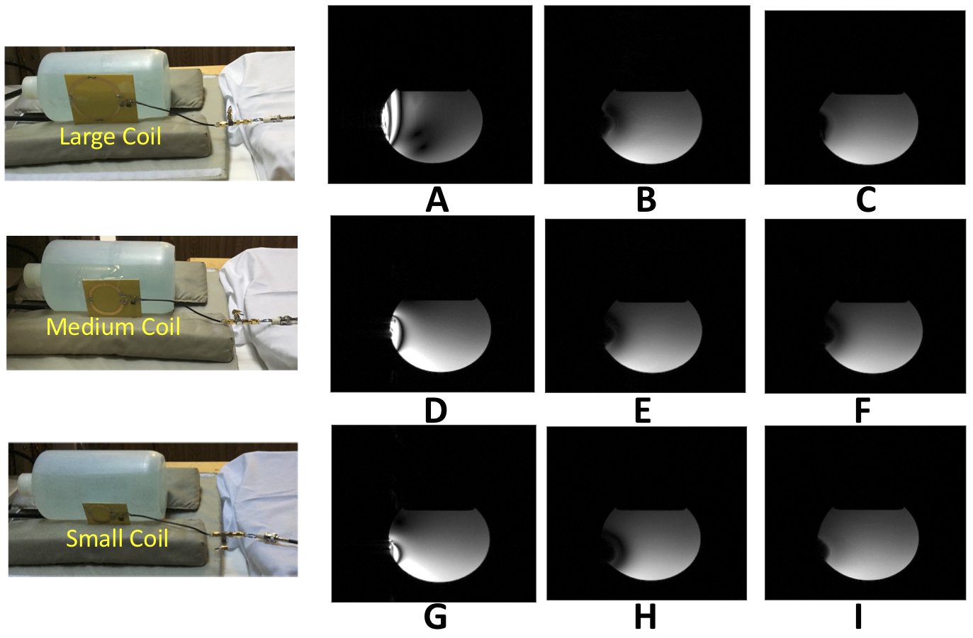
Given the induced voltage dependence on B1, different pulse sequences will transfer different amounts of power. The DC power from the rectifier was measured by a high-impedance oscilloscope via long coax through 1kΩ common mode resistors. The energy harvested per TR was calculated by integrating the output power (V2/R) over time for different load impedances. Figure 3 shows results for GRE sequences with a long TR of 150ms, 10ms TE, increasing flip angle and number of slices. D shows that the energy harvested for each coil is much higher with a 2 Ω load, since this is close to the optimal load for the series-resonant matched coils. However, A-C show that a 2 Ω load is not sufficient to hold a constant output voltage over the lengthy TR. With limited storage (& MR compatible) capacitance, a much higher resistance is required to lengthen the RC time constant. Figure 4 shows the energy harvesting results for a Fast GRE sequence, with 10ms TR. With shorter TR, smaller load resistors can be used, increasing the harvested energy. Figure 5 shows GRE images with TR of 150ms and flip angle of 60°. Harvesting power from the B1 field generates an RF current in the harvesting coil at the MRI frequency, causing banding artifacts in the MR image. These banding artifacts increase with increasing coil size and decrease with larger coil loading.Discussion & Conclusions
We were able to harvest 100s of µJ /TR through the use of high Q coils with a high efficiency class-E rectifier. The harvested power is highly dependent on pulse sequence RF duty-cycle - it is most feasible for high duty cycle sequences. However, B1 harvesting will generate flip angle banding when harvesting loops are near imaging regions. Separators that limit proximity may be useful, and orientation must ensure the loop surface is normal to B1. Ultimately, RF harvesting seems best suited to sub ~100mW levels of power delivery.Acknowledgements
We would like to thank GE Healthcare for their research support. This project is supported by NIH grant R01EB019241.References
1. Venkateswaran M, Johnson K, Weide DVD, Fain S. “Wireless powering using MRI pulse sequences”, Proceedings of the 24th Annual Meeting of ISMRM, 2016.
2. K. Byron, F. Robb, S. Vasanawala, J. Pauly, and G. Scott, “Switching Impedance Matching and Primary Coil Array Using RF MEMS Switches for a Wireless Power Transfer System.” Proc. Intl. Sco. Mag. Reson. Med. 26 (2018).
3. Suits, B. H., A. N. Garroway, and J. B. Miller. "Surface and gradiometer coils near a conducting body: the lift-off effect." Journal of magnetic Resonance 135.2 (1998): 373-379.
4. M. K. Kazimierczuk, “Analysis of class e zero-voltage-switching rectifier,” IEEE transactions on circuits and systems, vol. 37, no. 6, pp. 747–755, 1990.
Figures