1534
Wireless Power Transfer Compatibility and Noise Issues in MRI1Electrical Engineering, Stanford University, Stanford, CA, United States, 2GE Healthcare, Aurora, OH, United States, 3Radiology, Stanford University, Stanford, CA, United States
Synopsis
To achieve completely wireless coil arrays, several watts of power will need to be delivered with minimal impact on the MR images. Wireless power transfer (WPT) has been previously developed to efficiently transfer power, however, harmonics are generated and low frequency noise can be up-converted by both the DC-to-RF conversion and the RF-to-DC rectification of the WPT system. Efficiency can be traded off to reduce noise through additional filtering and rectifier choice, and by replacing the switching supply to the power amplifier with batteries an ultimate SNR performance within 6dB of the ideal can be achieved while continuously transferring power.
Introduction
Completely wireless coil arrays would increase patient comfort and improve workflow by removing the bulky baluns and cable traps required on cables in the magnet. These coil arrays would require several watts of power wirelessly delivered with minimal impact on the MR images. We have previously developed a gated wireless power transfer (WPT) system capable of delivering more than 10W inside the MRI with a DC-to-DC efficiency of about 63%1. Here, we examine different filtering, power supply and rectifier options in an effort to maintain the SNR of images acquired with the MRI coils while continuously delivering power.Methods
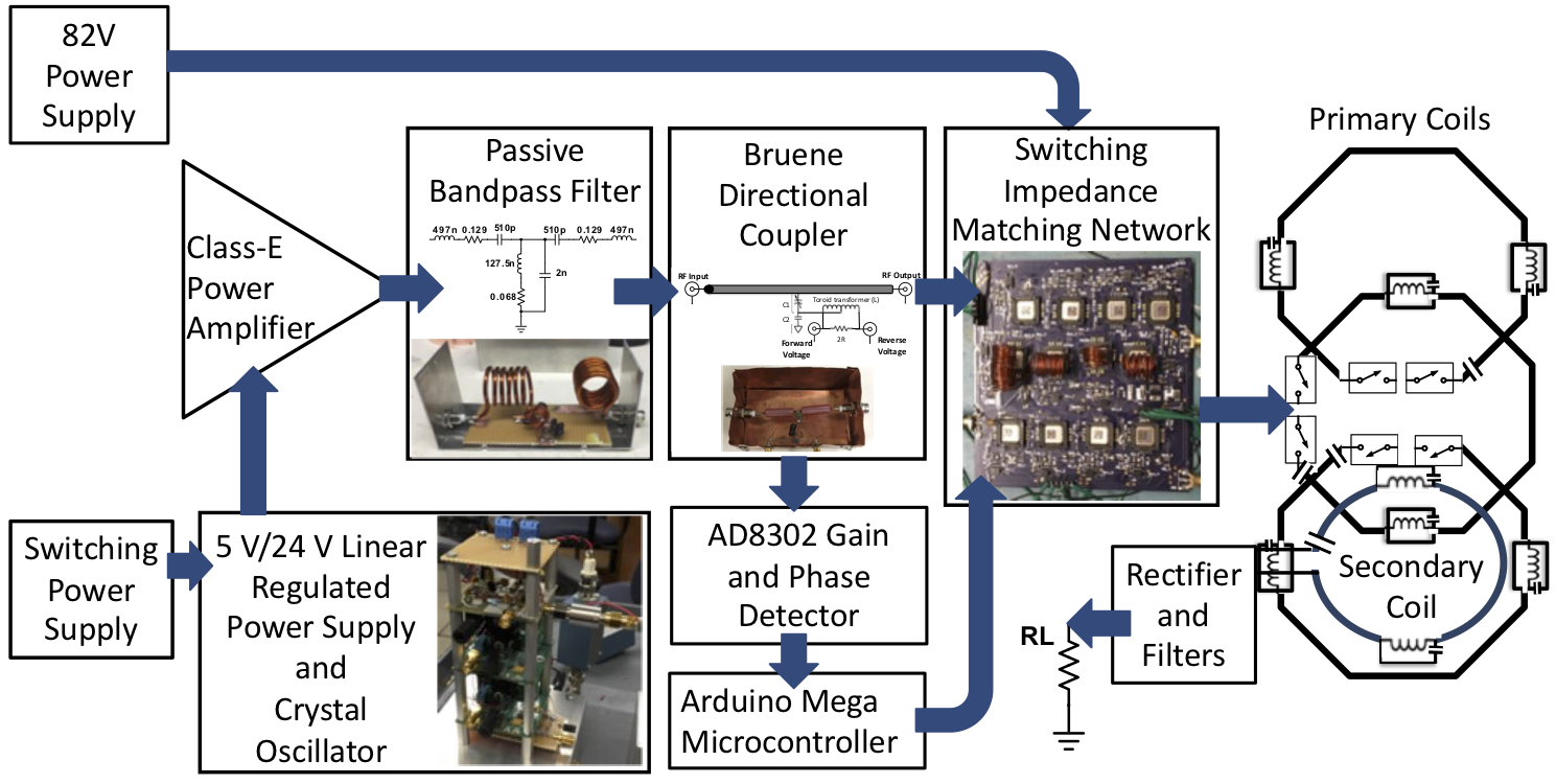
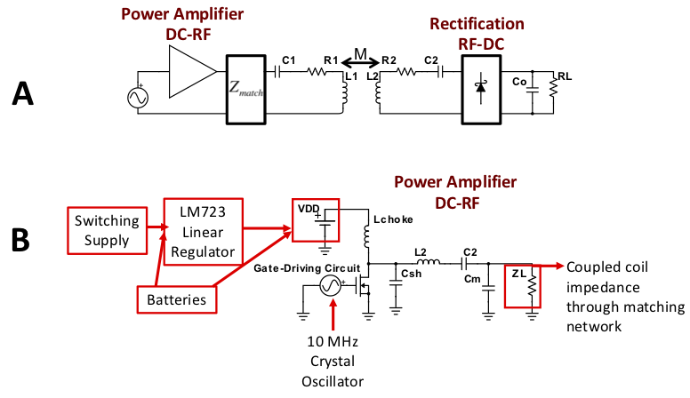
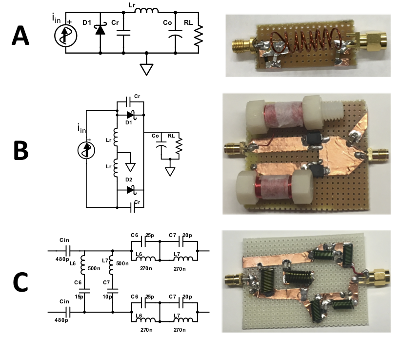
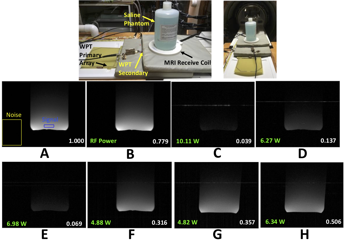
Our WPT system is shown in Fig.1 and described in detail in1,2. High efficiency is achieved using a class-E power amplifier, an array of primary coils with RF-MEMs control, a single secondary coil, and an automated RF-MEMs impedance matching network that maintains a constant load to the power amplifier in a dynamic environment. Harmonic output of the power amplifier is reduced by a passive band-pass filter but the system efficiency also reduces to around 55% while delivering ~10W. In the basic WPT schematic of Fig.2A, the coupled coils are series resonant at 10MHz to transfer RF power and a diode rectifier performs RF-DC conversion. The voltage supply for the power amplifier in Fig.2B is a switching supply followed by a linear regulator, however, batteries could be used instead to minimize any low frequency noise that could be up-converted by the power amplifier device acting as a switching mixer. Fig.3 shows the soft-switching based resonant class-E3 and full-wave class-E4 rectifiers that are utilized to minimize harmonic back-emission that can be detrimental in MRI. Full-wave class-E rectifiers have the added benefit of a near sinusoidal input waveform. An additional filter stage can also be added at the input of the rectifier, with notch filters at 60 and 70MHz to bracket the 1.5T MRI band.Results
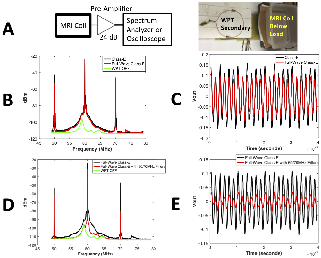
The DC-to-DC system efficiency was measured with the secondary coil aligned 3.5 cm above a primary coil in the array and delivering power to a 4W load resistor. With the class-E rectifier, the efficiency drops from about 55% to 39% with the addition of the notch filter, and with the full-wave class-E rectifier it drops from about 42% to 33% with the notch filter. Fig.4 shows the RF spectrum and voltage at the output of an MRI preamplifier connected to a loaded surface receive coil while transferring power nearby. As we expect, B-C show some noise reduction with the full-wave compared to the half-wave rectifier. However, there is still significant spectral growth around the 60MHz harmonic and while the voltage picked up by the MRI coil does not overload the preamplifier, it is around 220mVpeak-to-peak, which may block subsequent gain stages following the preamplifier. The addition of the notch filter in D-E significantly reduces the harmonic power, spectral spreading and voltage at the output of the preamplifier to around 63mVpeak-to-peak. Fig.5 demonstrates how these spectral changes translate into changes in image quality, where 1.5T images were acquired using MRI body coil transmit with a 5 inch (127mm) receive surface coil centered above the WPT coils. A GRE sequence was used with 24cm FOV, 6mm slice, TR of 150ms and TE of 15ms. The annotated relative signal-to-noise ratio (SNR) of each image was calculated using the outlined signal and noise regions and normalized with a reference image taken with all of the power supplies off. B shows relatively little SNR degradation when the rectifier is removed and only RF power is delivered. C-D and E-F show the significant improvement with the addition of the notch filter on the rectifier input, however in the best case combination the SNR is still only 31.6% of the reference. Replacing the voltage supply to the power amplifier with batteries further improves the SNR, achieving up to 50.6% of the reference SNR by eliminating the low frequency noise from the switching supply.Discussion & Conclusions
WPT is subject to strict requirements for compatibility in MRI, given that the limiting noise floor of MRI is thermal noise from the patient’s body. Harmonics are generated and low frequency noise can be up-converted around the harmonics by both the DC-RF conversion of the power amplifier and the RF-DC rectification of the WPT system. Efficiency can be traded off to reduce noise by additional filtering and a full-wave class-E rectifier with naturally lower harmonic generation. Replacing the switching supply to the power amplifier with batteries is also shown to reduce image degradation, resulting in an ultimate SNR performance within 6dB of the ideal while continuously transferring power. Operating continuous WPT without gating appears within reach in MRI.Acknowledgements
We would like to thank GE Healthcare for their research support. This project is supported by NIH grant R01EB019241.References
1. K. Byron, F. Robb, S. Vasanawala, J. Pauly, and G. Scott, “A Wireless Power Transfer System for MRI Scanners,” IEEE WPTC (2018).
2. K. Byron, F. Robb, S. Vasanawala, J. Pauly, and G. Scott, “Switching Impedance Matching and Primary Coil Array Using RF MEMS Switches for a Wireless Power Transfer System.” Proc. Intl. Sco. Mag. Reson. Med. 26 (2018).
3. M. K. Kazimierczuk, “Analysis of class e zero-voltage-switching rectifier,” IEEE transactions on circuits and systems, vol. 37, no. 6, pp. 747–755 (1990).
4. M. Liu, M. Fu, and C. Ma, “Low-harmonic-contents and high-efficiency class e full-wave current-driven rectifier for megahertz wireless power transfer systems,” IEEE Transactions on Power Electronics, vol. 32, no. 2, pp. 1198–1209 (2017).
Figures