1532
Design of multi-row multi-channel degenerate birdcage array coil based on minimum total reflection for the single-channel and circularly polarized modes of excitation1Department of Electrical and Electronics Engineering, Bilkent University, Ankara, Turkey, 2National Magnetic Resonance Research Center (UMRAM), Bilkent University, Ankara, Turkey
Synopsis
We propose that a transmit coil can be optimized for certain modes of operation. It is well-known that when the number of channels of a degenerate birdcage coil increases coupling between channels becomes a significant problem. The high total reflection when only one of its channels is used as a transmitter caused a small portion of the power delivered to the body. However, when it is properly designed, in some modes of operations such as circularly-polarized mode, the total reflection become negligibly small. In this work, we demonstrate this effect on various two-row degenerate birdcage-coils together with simulations and experiments.
Introduction
Transmit array (TxArray) coils are being widely investigated for ultra-high field systems in order to obtain a homogeneous excitation. These coils can be also very useful for the conventional scanners since, without any increase in the cost, they will provide degrees of freedom to the designer of pulse sequencer. This freedom may be used, for example, to increase the power efficiency1-3 or to implement implant-friendly mode4 in a very efficient way.
In TxArrays, however, the coupling between channels is a significant problem. This problem gets more difficult to solve as the number of channels increases5. It should be noted that the power efficiency of the TxArray coil is a function of the phase and amplitude of the input power. The reflected power can be written as $$$P_{reflected}=\frac{1}{2}\frac{|V^{-}|^{2}}{Z_{0}}$$$ where $$$V^{-}$$$ denotes the reflected voltage vector given in the phasor form. $$$V^{-}$$$ can be written as $$$V^{-}={\bf{S}}V^{+}$$$ where $$$\bf{S}$$$ denotes the scattering matrix and $$$V^{+}$$$ denotes the incident voltage. As can be noted in this formulation, in order to obtain zero reflection for all incident voltages, $$$\bf{S}$$$ has to be zero. However, for a non-zero $$$\bf{S}$$$-matrix, zero reflected power can still be obtained for certain input voltages.
In this study, we claim that is possible to design an array coil such that its total reflected power is zero or low in some important modes of operation. For this purpose, we designed a double-row degenerate birdcage coil that operated in the circularly-polarized (CP) mode with very low reflection while its single-channel (SC) operation mode has an acceptable reflection level. Note that if the degenerate birdcage coil is used in the CP mode, its excitation profile will be similar to the profile of a conventional birdcage coil6-9.
Methods
We simulated 4 shielded degenerate birdcage head TxArrays with varying number of channels and the same overall dimensions loaded with a uniform cylindrical phantom shown in Fig.1. Transmit loops distributed in both the circumferential and the z-direction and could be decoupled by adjustment of decoupling capacitors placed between nearest neighbors. Exciting both rows separately in the CP mode, while the currents of the upper and lower rows cancel each other in their mutual ring segment, provides the ability of the CP mode excitation by this type of TxArrays same as conventional birdcage coils6-9.
Fig.2 depicts an arbitrary N-port microwave network. The normalized-TR for the nth port of this network, when the characteristic impedance is real, can be defined as10:
$$TR_n=\frac{P_{reflected_{n}}}{P_{incident_{n}}}=|\frac{V_n^-}{V_n^+}|^{2}$$
By adjusting capacitor values, S-matrix can be optimized to minimize the TR value such that CP mode of operation is obtained with very low reflection. The optimization problem is a non-convex problem and it also gives us the opportunity to minimize the TR in additional modes of operations as well. For this, we chose the SC mode. In this mode, the TR can be expressed as $$$\sum_{n=1}^N|S_{mn}|^{2}$$$. To evaluate the performance of this idea, the coils capacitors are found using the co-simulation strategy11 with the criteria to minimize TR in both CP and SC modes.
Results and discussion
We assessed the performance of the TxArrays at 123.2MHz shown in Fig.3 in the SC mode and two different CP modes. In CP1 mode, both rows individually excited with identical power and linearly increasing phase, whereas the lower-row channels excited with a 180° phase shift relative to axially adjacent upper-row channels, while in the CP2 mode, both rows are in the same phase. In both CP1 and CP2 modes, TR is less than 1% for all coils. In the SC mode of operation, however, the TR increases with the increased number of channels.
Fig.4 shows the surface current density on 2x4-channels DBC, and the B1+-maps inside of the phantom for the SC, CP1, and CP2 modes. As it is obvious, the current on the TxArray’s middle-ring is almost zero in the CP1 mode which provides the possibility of having a uniform B1+-profile in the iso-center. Additionally, for the CP2 mode, the B1+-field is almost zero in the central slice while the profiles in the other slices are homogeneous which make this coil to use for some safety applications and multi-slice imaging.
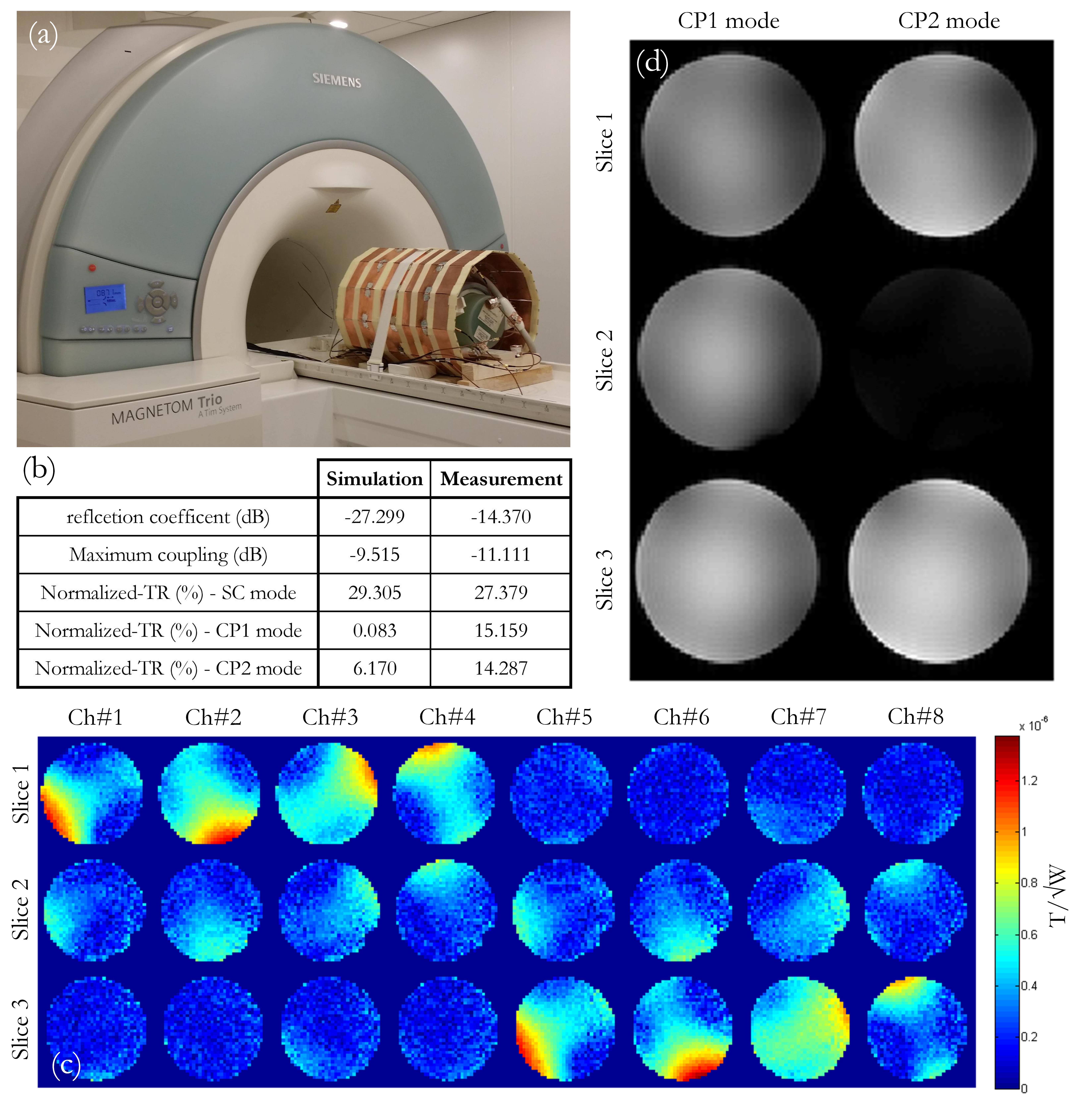
As proof of the method, the structure of 2×4-channels TxArray constructed (Fig.5(a)). The reflection coefficient, maximum coupling, TR, B1+-profile of each individual channel, and GRE images of the CP1 and CP2 modes are shown in Fig.5(b-d).
Conclusion
Here we introduced a methodology for designing of DBC based on minimization of the TR for certain modes of operations. Our simulations show that although the coupling ratio is rising with increasing the number of channels, the TR remains very low and the power TxArray efficiencies high in the CP modes.Acknowledgements
No acknowledgement found.References
[1] Childs AS, Malik SJ, O'Regan DP, Hajnal JV. Impact of number of channels on RF shimming at 3T. Magnetic Resonance Materials in Physics, Biology and Medicine. 2013:1–10.
[2] Kozlov M, Turner R. Analysis of RF transmit performance for a multi-row multi-channel MRI loop array at 300 and 400 MHz. 2011. IEEE. p 1190-1193.
[3] Guérin B, Gebhardt M, Serano P, Adalsteinsson E, Hamm M, Pfeuffer J, Nistler J, Wald LL. Comparison of simulated parallel transmit body arrays at 3 T using excitation uniformity, global SAR, local SAR, and power efficiency metrics. Magn Reson Med 2015; 73(3):1137-1150.
[4] Eryaman Y1, Guerin B, Akgun C, Herraiz JL, Martin A, Torrado-Carvajal A, Malpica N, Hernandez-Tamames JA, Schiavi E, Adalsteinsson E, Wald LL. Parallel transmit pulse design for patients with deep brain stimulation implants, Magn Reson Med. 2015 May;73(5):1896-903.
[5] Mahmood Z, Guerin B, Adalsteinsson E, Wald L, Daniel L. An Automated Framework to Decouple pTx Arrays with Many Channels. 2013:2722.
[6] Alagappan V, Nistler J, Adalsteinsson E, Setsompop K, Fontius U, Zelinski A, Vester M, Wiggins GC, Hebrank F, Renz W. Degenerate mode band‐pass birdcage coil for accelerated parallel excitation. Magn Reson Med 2007; 57(6):1148-1158.
[7] Sadeghi-Tarakameh A, Kazemivalipour E, Demir T, Gundogdu U, Atalar E. Design of a Degenerate Birdcage Radiofrequency Transmit Array Coil for the Magnetic Resonance Imaging Using Equivalent Circuit Model. In Proceeding of the 34th Annual Scientific Meeting of ESMRMB, Barcelona, Spain 2017:300-301.
[8] Kazemivalipour E, Sadeghi-Tarakameh A, Yilmaz U, Acikel V, Sen B, Atalar E. A 12-Channel Degenerate Birdcage Body Transmit Array Coil for 1.5T MRI Scanners. In Proceeding of the 26th Joint Annual Meeting ISMRM-ESMRMB, Paris, France 2018: Abstract 1708.
[9] Sadeghi-Tarakameh A, Kazemivalipour E, Demir T, Gundogdu U, Atalar E. Accelerating the Co-Simulation Method for Fast Design of Transmit Array Coils: An Example Study on a Degenerate Birdcage Coil. In Proceeding of the 26th Joint Annual Meeting ISMRM-ESMRMB, Paris, France 2018: Abstract 4404.
[10] Pozar DM. Microwave engineering: John Wiley & Sons, 2009.
[11] Kozlov M, Turner R. Fast MRI coil analysis based on 3-D electromagnetic and RF circuit co-simulation. Journal of Magnetic Resonance. 2009; 200(1):147–152.
Figures