1531
Investigation of an artificial line π LC BALUN as a single-stage impedance transformation network, for direct preamplifier and coil matching in MRI surface array coils.1Technology Innovation Department, Society for Applied Microwave Electronics Engineering and Research, Mumbai, India
Synopsis
Previous studies have shown that the coil matching network (CMN) and preamplifier input matching network (IMN) can be combined to match the coil loop to the transistor in the preamplifier directly. Through simulations we have shown that the artificial line ‘π’ LC BALUN can be used to match the coil loop to the transistor in the preamplifier directly. Though ‘L’ section LC BALUN is widely used in surface array coils to create high blocking impedance across coils, it has several limitations. Hence, artificial line LC BALUN can be used as impedance transformation network and as a common-mode choke simultaneously.
INTRODUCTION:
In a surface array coil, coupling between adjacent coil elements can be reduced by creating high blocking impedance at each coil elements. Each coil element in an array has three noise signal components viz. thermal noise (Vn_th), coupled signal (Vcp_signal) and coupled thermal noise (Vcp_n_th) from the adjacent coil element. Total noise voltage of a coil element in a two-element array is given by equation 1.
$$Vnoise_total_coil 1 = Vcp_signal_coil 2 + sqrt((Vn_th^2) + (Vcp_n_th_coil 2^2)) = ((ω*Lcoil*k*Vcoil 2)/(R2 + Zblock)) + sqrt((4*K*T*Δf*Rcoil 1) + (4*K*T*Δf*((Lcoil^2)*(k^2)/(Rcoil 2 + Zblock))))$$ 1
Where,k is coefficient of coupling between coil 1 and coil 2 placed close to each other. According to equation 1, as Zblock increases, total noise voltage of the coil approaches its minimum value which increases the SNR of an array1.
Additionally, by reducing inter-element coupling, high blocking impedance across coil elements also helps to optimize the coil array for parallel imaging. Critically overlapped coil elements in an array is another way to reduce inter-element coupling. However, critical overlapping is not desirable from the perspective of the algorithms used to construct MR images (SMASH/GRAPPA). In parallel imaging, the sensitivity difference between two adjacent coils is inversely proportional to the noise in the reconstructed image. Hence, to increase the SNR of parallel imaging, under-lapping (maintaining a gap between two coils) or in some cases extra-lapping (more than critical overlapping) is the optimum solution2,3.
Conventionally, high blocking impedance at the coil elements is created by using coil matching network (CMN). Past studies have used ‘L’ section of inductor and capacitor as a CMN to produce a blocking impedance that is on the order of 100 to 500 Ω; which is directly proportional to the coil size and depends on coil loading4. Several attempts have been made to create blocking impedance using ‘L’ sections LC BALUN5,6, however they created blocking impedance of conventional values i.e. 50, 75 and 300 Ω. Previous attempts also imposed restrictions of low input impedances on the preamplifier to create high blocking impedance and included a step-down transformer to bring down the input impedance of preamplifier even further to increase the blocking impedance6. Several studies also used other methods for improving decoupling in a surface coil array e.g. capacitive and inductive decoupling7,8, decoupling through induced current compensation or elimination (ICE)9 etc. But these methods impose restrictions on coil’s fabrication and coil’s placement, decreasing the flexibility required for parallel imaging coil optimisation.
Cao et al.10 combine the coil matching network (CMN) and input matching network (IMN) of the preamplifier (LNA) to create a high blocking impedance (Zblock) across the coil and simultaneously terminate the LNA with its optimum input impedance (Zopt) for noise matching. Such a combination will eliminate the need of two separate networks and reduces the noise figure of the entire receiver chain. We can form an artificial line LC BALUN11 with such networks which can act as impedance transformation networks as well as a common-mode choke.
METHODS:
$$L = sqrt(Zcoil*Zopt^*)/ωO$$ 2
$$C = 1/(ωO*sqrt(Zcoil*Zopt^*))$$ 3
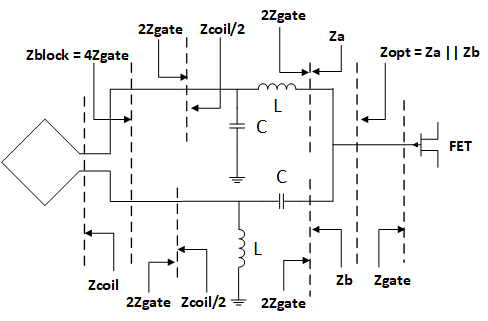
According to equation 2 and 3, the product of Zcoil and Zopt* has to be real and positive to get real values of BALUN components. According to Li et al.12, Addition of extra inductor or capacitor on source side or load side of BALUN to get real values of BALUN components, degrades the desired S-parameters of BALUN. An artificial line ‘π’ LC BALUN achieves matching without the degradation.
$$Za = Zb = (-sin(β)*2*Zgate*((j*2*Zgate*sin(β)) - (Zcoil/2*cos(β))))/(j*(cos(β)^2*(Zcoil/2) - (Zcoil/2)) + (sin(β)*cos(β)*2*Zgate))$$ 4
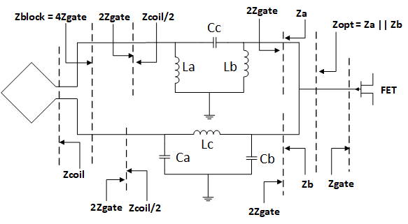
Equation 4 shows the relationship between Zcoil, Zgate and Zopt (Za||Zb) for BALUN shown in figure 2.
RESULTS:
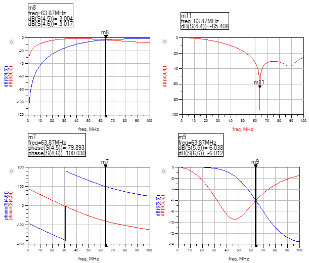
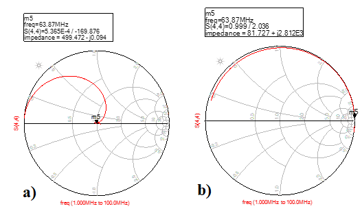
Figure 3 shows the S parameters of artificial line ‘π’ LC BALUN for 63.87 MHz (for 1.5 T MRI). Figure 4 shows the transformed impedance values of artificial line ‘π’ LC BALUN for 63.87 MHz (for 1.5 T MRI).DISCUSSION:
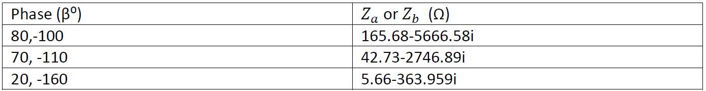
According to figure 3, S-parameters of artificial line π LC BALUN were matched with the desired S-parameters of general LC BALUN network i.e. return loss at differential ports is -6 dB, insertion loss at both differential ports is -3 dB, return loss at single ended port is as low as possible and phase difference between differential ports is 180⁰. According to figure 4 impedances have been transformed as per equation 4 and table 1.CONCLUSION:
Artificial line LC BALUNs, can present high input impedance of the LNA’s first stage FET (Zgate) across the coil and transform the coil’s impedance (Zcoil) into the optimum input impedance of the LNA (Zopt) for noise matching. Thus we can simultaneously use a BALUN as a common-mode choke and as an impedance transformation network between pre-amplifier and coil, reducing the number of matching stages.Acknowledgements
Authors are thankful to Mr. Bhaskara Naik, Mr. Shrikant Sonawane, Mr. Neeraj Yadav and Mr. Rohit Apurva for their support.References
- Tobgay S. Novel concepts for RF surface coils with integrated receivers, M.S. Thesis. Worcester Polytechnic Institute at Worcester; April 2004.
- PD Dr. med. Stefan O. Schoenberg, Dr. rer. nat. Olaf Dietrich, et al., Parallel Imaging in Clinical MR Applications, Springer-Verlag Berlin Heidelberg, 2007, eBook ISBN: 978-3-540-68879-2.
- G. R. Duensing, S. Vijayakumar, S. B. King, The Effect of Over/Underlap of Surface Coil Elements on AP Direction Acceleration, Proc. ISMRM 14 (2006).
- US Patent: US 8.207,736 B2, Jun. 26, 2012.
- de Zwart, J. A., Ledden, P. J., Kellman, P. , van Gelderen, P. and Duyn, J. H. (2002), Design of a SENSE‐optimized high‐sensitivity MRI receive coil for brain imaging. Magn. Reson. Med., 47: 1218-1227. doi:10.1002/mrm.10169
- G. C. Nascimento, F. F. Paiva, and A. C. Silva, An Inductively Decoupled Coil Array for Parallel Imaging of Small Animals at 7T, Proc. Intl. Soc. Mag. Reson. Med. 16 (2008).
- B. Wu, P. Qu, Y. Pang, G. X. Shen, LC Decoupling Circuit for Arbitrarily placed Coils, Proc. Intl. Soc. Mag. Reson. Med. 14 (2006).
- G. C. Nascimento, F. F. Paiva, A. C. Silva, Inductive Decoupling of RF Coil Arrays: A Study at 7T, Proc. Intl. Soc. Mag. Reson. Med. 14 (2006).
- Li, Y. , Xie, Z. , Pang, Y. , Vigneron, D. and Zhang, X. (2011), ICE decoupling technique for RF coil array designs. Med. Phys., 38: 4086-4093. doi:10.1118/1.3598112
- Xueming Cao, Elmar Fischer, Jürgen Hennig, Maxim Zaitsev, Direct matching methods for coils and preamplifiers in MRI, Journal of Magnetic Resonance, Volume 290, Pages 85-91, 2018.
- Fredrick E. Terman, Electronic and Radio Engineering, McGraw-Hill 4th Ed. 1955.
- Richard Chi-Hsi Li, RF Circuit Design, John Wiley & Sons, Inc., 2009.
Figures