1529
Triple Tuned 6-element Asymmetric Mode Ladder-Resonator/Transceive-Array for Thoracic Imaging of 19F/1H at 1.5T and 129Xe/19F at 3T1Unit of Academic Radiology, University of Sheffield, Sheffield, United Kingdom, 2GE Healthcare Inc., Aurora, OH, United States
Synopsis
A 6-element triple-tuned asymmetric mode ladder-resonator/transceive-array was constructed in order to allow direct field strength comparisons of 19F/1H imaging at 3T and 1.5T using the same coil geometry, and to compare 129Xe and 19F imaging at 3T. The designed array is the first instance of triple-tuning a coil by replacing tuning capacitors with LC networks to provide the equivalent reactance needed for coil tuning at three Larmor frequencies (35MHz, 60MHz and 120MHz). Details on construction and simulation are provided and phantom imaging performed for 19F/1H at 1.5T and 19F at 3T, as well as in-vivo imaging of hyperpolarized 129Xe at 3T, demonstrate the functionality of the coil.
Background
Inert gas MRI, using hyperpolarized gases (129Xe or 3He) or fluorinated gases (19F with C2F6, S6, C3F8), delivers images of the lung that are directly sensitive to ventilation and gas exchange1. Ventilation imaging with both 19F and 129Xe provides complementary information: 129Xe has higher signal for ventilation2,3 and dissolves into the blood4-6, while 19F can be used for free-breathing imaging to characterize washout dynamics7. However, it is not clear what the optimal field strength for 19F imaging is8. Therefore, it would of interest to have an RF coil with the same geometry in order to directly compare and benchmark 129Xe, 19F and 1H imaging exams at the same field strength. It has been shown that for body-sized coils, with loading that is largely body dominated, dual-tuning has a minimal impact on efficiency9. Also, it has been demonstrated that a coil tuned to 19F can be used for 1H imaging with suitable performance10-13.Purpose
To design the first triple-tuned homogeneous RF transceive array for in-vivo lung MRI to allow co-registered acquisition of signals from 129Xe and 19F at 3T (Philips Ingenia), and also 19F at 1.5T (GE HDx) for direct comparison of 19F/1H lung MRI at the two field strengths.Methods
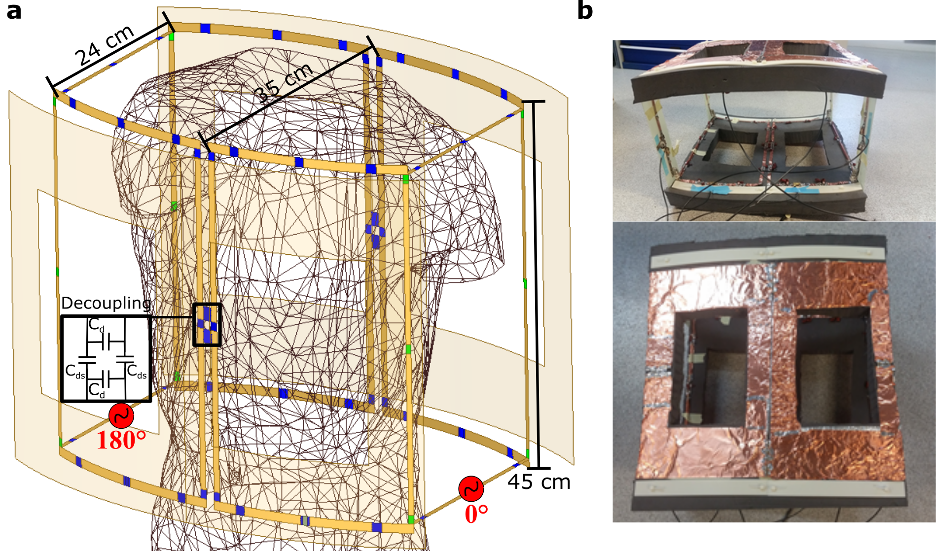
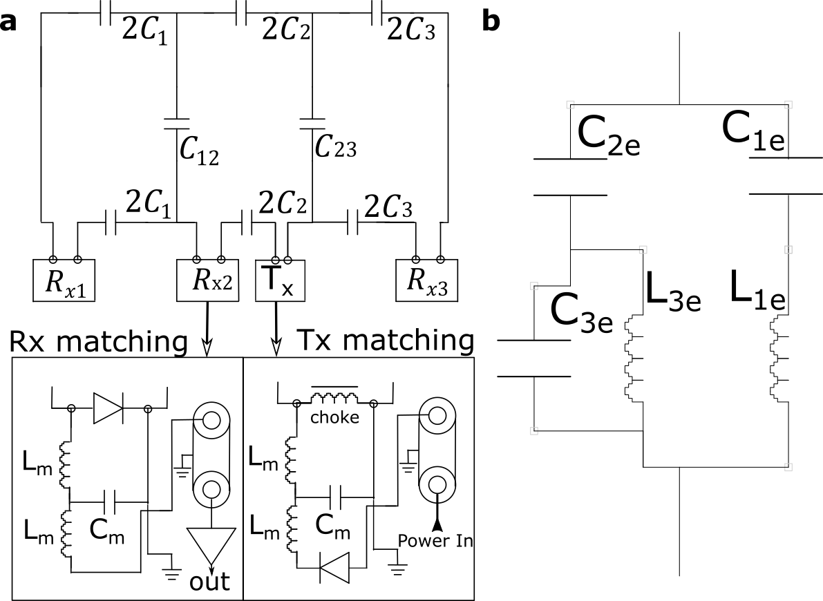
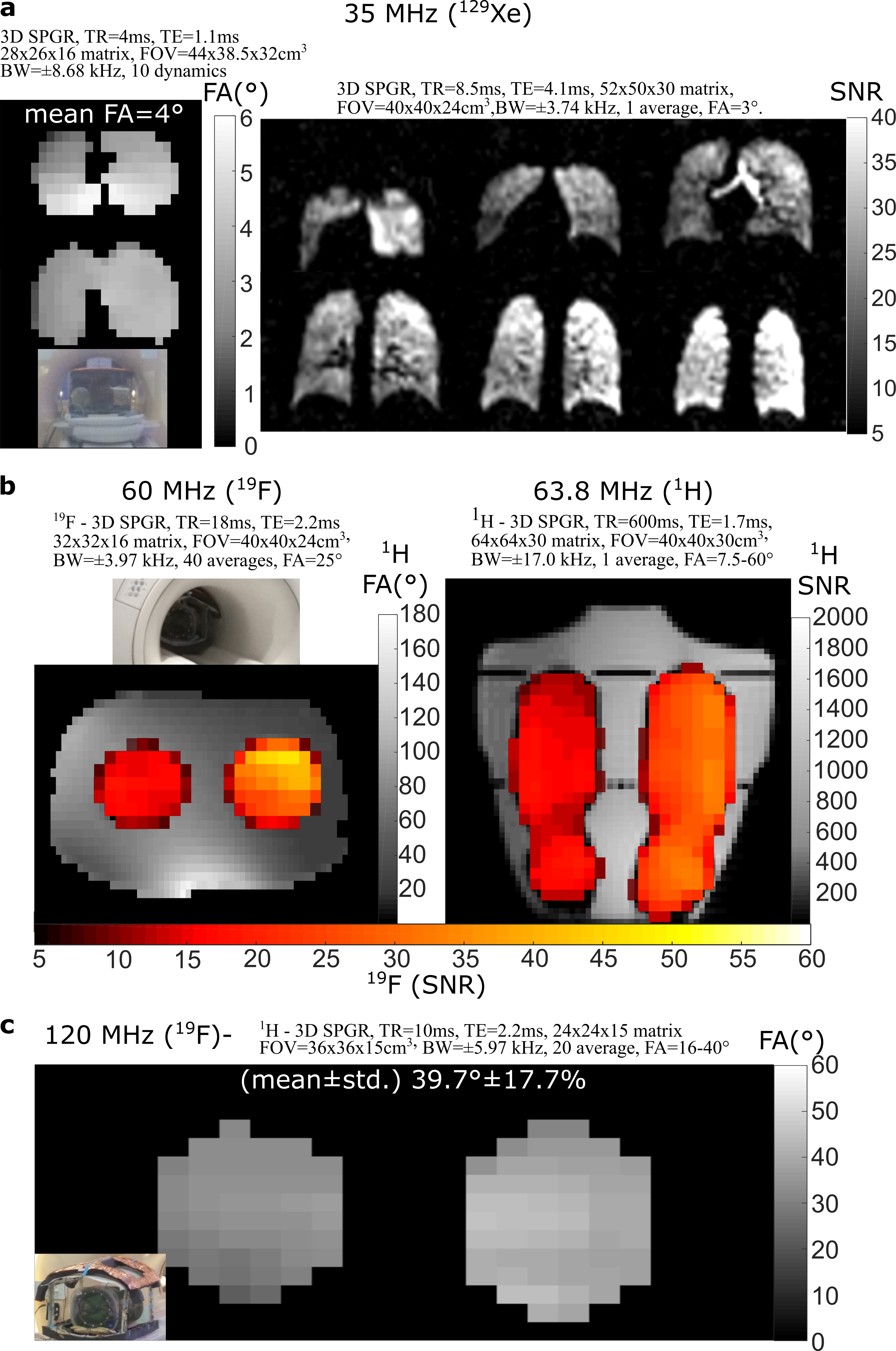
The simulation model (ANSYS,HFSS), with male human body model, is provided in Figure 1a, showing the geometric design of the 6-element ladder/transceive array hybrid coil. Capacitor values to achieve the desired current distribution for circular polarization at the three frequencies are derived as in reference (10). In the constructed coil (Figure 1b), a metal shield, split up with high value capacitor bridges, is employed to reduce radiative losses at 3T, focus the field and prevent interaction with the 1H body coil and scanner bore RF shield14,15,16. The equivalent circuit schematic for a three-mesh half of the 6-element transceive array is shown in Figure 4. To triple-tune the coil, the capacitors distributed along the coil are replaced with the network shown in Figure 2b. Currently, matching was adjusted when imaging the different nuclei, but will be replaced with triple tuned equivalents in the future. The capacitor values for the tuning capacitors (Figure 2a) and the decoupling capacitors (Figure 1a) at the three different frequencies are listed in Figure 3. Measurement of the equivalent series resistance (ESR) and capacitance (Figure 2b) was performed by measuring the Q factor of a rectangular coil17 tuned to the desired frequency with two capacitors (Dalian, 10C), one which matched the desired value in Table 1, then calculating the ESR as the difference in coil resistance when replaced with the triple-tuned capacitor equivalent. Phantom imaging with 19F at 1.5T and 3T, and 1H at 1.5T, was performed with a torso shaped shell filled with 1.96g/L-CuSO4 and 3.6g/L-NaCl solution and bottles of 81% C3F8+ 21%O2. FA mapping was performed by fitting to the SPGR equation with varying power13. At 3T, 129Xe in-vivo imaging was performed following informed consent using a protocol approved by the UK National research ethics committee. A volunteer inhaled 500mL of hyperpolarized 129Xe18 for FA mapping and again for ventilation imaging. Imaging parameters are included with imaging results in Figure 5.Results
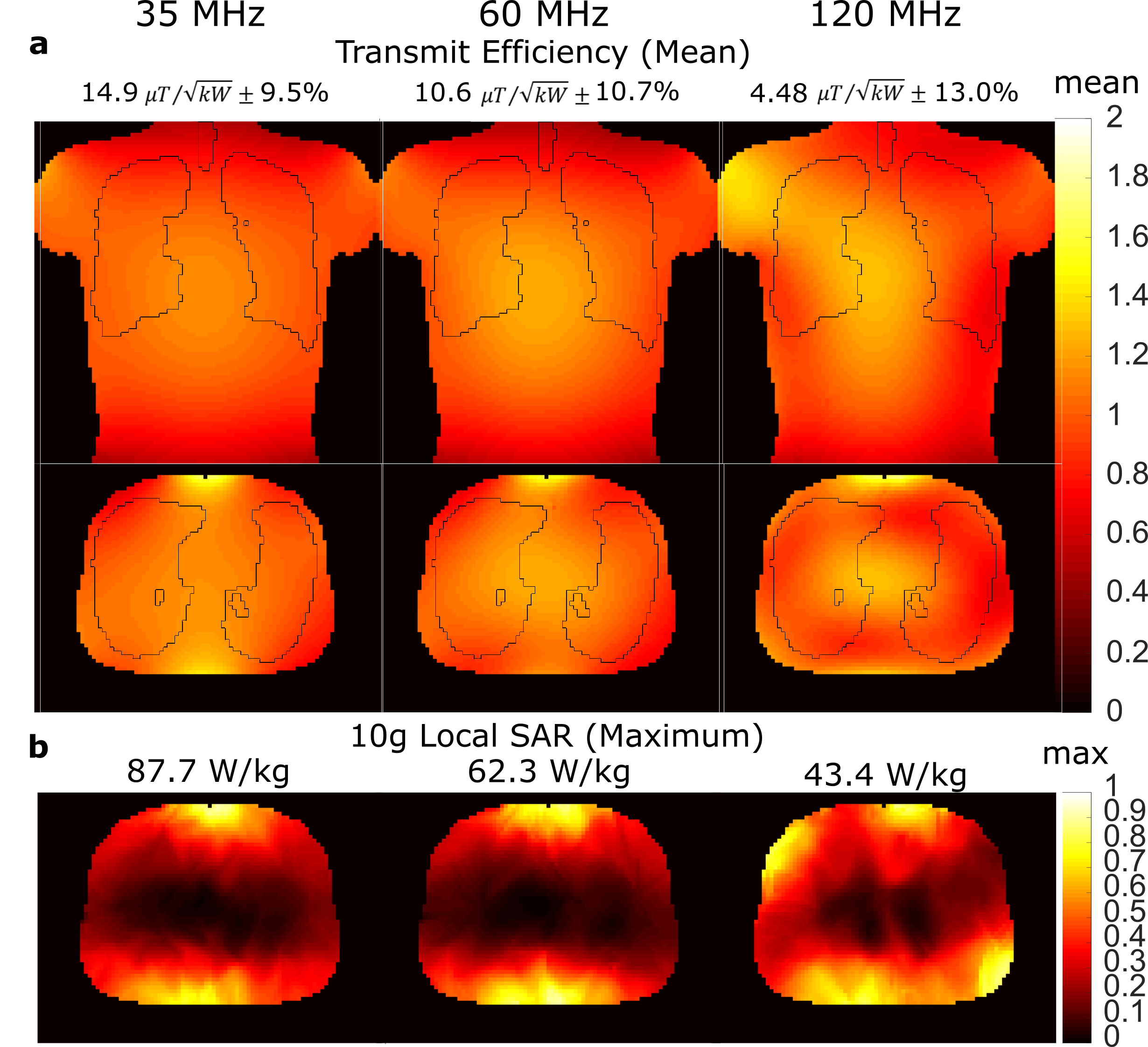
The simulated transmit efficiency for 1kW RMS power are shown in Figure 4a. The simulated transmit efficiency follows a nearly linear trend with frequency and homogeneity decreases as frequency increases. The ESRs of the triple-tuned capacitors in Table 1 are small relative to the loaded self-resistance of the coils (2.3Ω/21Ω/50Ω at 35MHz/60MHz/120MHz for central mesh). The results of 10g local SAR simulation is shown in Figure 4b demonstrating that the distribution of SAR remains similar from 35MHz to 60MHz, but additional “hot-spots” are observed at 120MHz. The result of imaging experiments for SNR and FA mapping are shown in Figure 5 (129Xe-Figure 5a/19F+1H at 1.5T-Figure 5b/19F at 3T-Figure 5c), demonstrating that the coil was successfully employed to image the targeted nuclei. FA maps (35MHz and 120MHz) show measured homogeneity is comparable to simulation and FA maps for 1H at 1.5T demonstrate that the coil may still be employed off-resonance for structural imaging.Discussion and Conclusion
To the best of our knowledge, this is the first demonstration of a triple-tuned transceive-array, which was employed for imaging at four different Larmor frequencies:19F/1H at 1.5T (60MHz/64MHz), and 129Xe/19F at 3T (35MHz/120MHz); imaging at 1H (128 MHz) may also be achievable in the future. The low ESRs relative to the coil’s loaded resistance indicate that neither the transmit efficiency or receive sensitivity are significantly degraded, but more comprehensive tests are required, such as comparison to single tuned volume coils and further in-vivo ventilation imaging.Acknowledgements
Doctoral program funding for Adam Maunder was partially provided by support from GE Healthcare Inc. and scholarships from the Natural Sciences and Engineering Research Council of Canada (NSERC) and University of Sheffield. This work was funded by the National Institute for health research (NIHR), Medical Research Council (MRC) and University of Sheffield Hyperpolarised Imaging Group - POLARIS. The views expressed in this abstract are those of the author and not necessarily those of NHS, NIHR, MRC or the Department of Health.References
1 Couch, M. et al. Hyperpolarized and Inert Gas MRI: The Future. Mol Imaging Biol 17, 149-162, doi:10.1007/s11307-014-0788-2 (2015).
2 Stewart, N. et al. Comparison of 3 He and 129 Xe MRI for evaluation of lung microstructure and ventilation at 1.5 T. Vol. 48 (2016).
3 Stewart, N. J., Norquay, G., Griffiths, P. D. & Wild, J. M. Feasibility of human lung ventilation imaging using highly polarized naturally abundant xenon and optimized three-dimensional steady-state free precession. Magnetic Resonance in Medicine 74, 346-352, doi:doi:10.1002/mrm.25732 (2015).
4 Norquay, G. et al. Relaxation and exchange dynamics of hyperpolarized 129Xe in human blood. Magn Reson Med 74, 303-311, doi:10.1002/mrm.25417 (2015).
5 Leung, G., Norquay, G., Schulte, R. F. & Wild, J. M. Radiofrequency pulse design for the selective excitation of dissolved 129Xe. Magnetic Resonance in Medicine 73, 21-30, doi:10.1002/mrm.25089 (2015).
6 Chan, H. F., Stewart, N. J., Norquay, G., Collier, G. J. & Wild, J. M. 3D diffusion‐weighted (129)Xe MRI for whole lung morphometry. Magnetic Resonance in Medicine 79, 2986-2995, doi:10.1002/mrm.26960 (2018).
7 Gutberlet, M. et al. Free-breathing Dynamic 19F Gas MR Imaging for Mapping of Regional Lung Ventilation in Patients with COPD. Radiology, 170591, doi:10.1148/radiol.2017170591 (2017).
8 Maunder, A., Rao, M., Robb, F. & Wild, J. M. Optimization of steady-state free precession MRI for lung ventilation imaging with (19) F C3 F8 at 1.5T and 3T. Magn Reson Med, doi:10.1002/mrm.27479 (2018).
9 Isaac, G., Schnall, M. D., Lenkinski, R. E. & Vogele, K. A design for a double-tuned birdcage coil for use in an integrated MRI/MRS examination. Journal of Magnetic Resonance (1969) 89, 41-50, doi:http://dx.doi.org/10.1016/0022-2364(90)90160-B (1990).
10 Maunder, A., Robb, F., Rao, M. & Wild, J. Application of Asymmetric Mode Ladder Resonators for Improved Efficiency of Individual Elements in Transceive Arrays. Proc. Intl. Soc. Mag. Reson. Med. 26, 4273 (2018).
11 Maunder, A., Rao, M., Robb, F. & Wild, J. M. Optimization of Steady-State Free Precession MRI for Lung Ventilation Imaging with 19F C3F8 at 1.5 T and 3T. Magnetic Resonance in Medicine (2018).
12 Maunder, A., Rao, M., Robb, F. J. L. & Wild, J. M. Combined Transmit Array and 8-Channel Receive Coil Array for 19F/1H for Human Lung Imaging at 1.5 T Utilizing MEMS Transmit-Receive Detuning. Proc. Intl. Soc. Mag. Reson. Med. 25, 1052 (2017).
13 Maunder, A., Rao, M., Robb, F. & Wild, J. M. Comparison of MEMS switches and PIN diodes for switched dual tuned RF coils. Magnetic Resonance in Medicine 80, 1746-1753, doi:doi:10.1002/mrm.27156 (2018).
14 Gilbert, K. M. et al. Transmit/receive radiofrequency coil with individually shielded elements. Magnetic Resonance in Medicine 64, 1640-1651, doi:10.1002/mrm.22574 (2010).
15 Doty, F. D., Entzminger Jr, G., Hauck, C. D. & Staab, J. P. Practical Aspects of Birdcage Coils. Journal of Magnetic Resonance 138, 144-154, doi:http://dx.doi.org/10.1006/jmre.1998.1703 (1999).
16 Alecci, M. & Jezzard, P. Characterization and reduction of gradient-induced eddy currents in the RF shield of a TEM resonator. Magn Reson Med 48, 404-407, doi:10.1002/mrm.10226 (2002).
17 Mispelter, J., Lupu, M. & Briguet, A. NMR Probeheads for Biophysical and Biomedical Experiments: Theoretical Principles & Practical Guidelines. (Imperial College Press, 2006).
18 Norquay, G., Collier, G. J., Rao, M., Stewart, N. J. & Wild, J. M. 129Xe-Rb Spin-Exchange Optical Pumping with High Photon Efficiency. Physical Review Letters 121, 153201, doi:10.1103/PhysRevLett.121.153201 (2018).
Figures