1528
A transceive array with passively fed dipoles and shielded loop coils for laryngeal imaging at 7T1C.J. Gorter Center for High Field MRI, Leiden University Medical Center, Leiden, Netherlands
Synopsis
A transceive array for laryngeal imaging at 7T was constructed, consisting of 5 shielded loop coils and 3 passively fed dipoles. The array is physically flexible due to the absence of lumped elements in the loops and shows very high inter-element isolation (greater than -19 dB) without implementing decoupling circuits, even though the elements are closely packed. After RF shimming using the array, high resolution turbo spin-echo images were acquired from a healthy volunteer.
Introduction
Imaging the larynx in high detail is critical for assessing laryngeal tumors and choosing a treatment plan. Even though imaging the larynx is not easily performed due to extensive movement in the region and the lack of a commercially available coil, dedicated custom-built receive coils at 3T have shown to be beneficial for image quality.1
Further improvements can potentially be achieved by going to higher field strengths, but obtaining such images becomes much more difficult due to the absence of a specific transmit coil for the larynx. Additionally, the presence of large B0 inhomogeneities in this anatomy due to tissue-air interfaces limits the use of gradient echo sequences, meaning that turbo spin-echo (TSE) sequences are needed, with the associated higher specific absorption rate (SAR) and signal dependence on the tip angle.
In this work we present an eight-element highly decoupled transceive array at 7T consisting of both shielded loop coils and passively fed dipoles, specifically designed to fit tightly around the larynx. RF shimming in the region of the larynx was performed in order to obtain as homogeneous a B1+ field as possible for TSE imaging.
Materials and Methods
The transceive array was constructed of 5 shielded loop coils and 3 passively fed dipoles. (Figure 1) The array is flexible due to the absence of lumped elements in the loops and was formed to fit the neck of a healthy volunteer. The shielded loop coils2 (Figure 2) with a diameter of 10 centimeters were constructed from coaxial cable (Huber+Suhner ‘K 02252 D-06’, diameter 3.0 mm) with a balanced capacitive matching network. The passively fed dipoles (Figure 3) were adapted from reference 3 and constructed on Rogers RT6035HTC 0.75 mm PCB. One side of the PCB contains a small feeding dipole. The other side of the PCB contains the larger radiating dipole and is oriented towards the patient. The dipoles are intrinsically geometrically decoupled from the underlying loops.4 The eight-channel transceive array was connected to a Philips 7T Multix system and phase RF shimming was performed using eight individual transmit channels in order to optimize the transmit homogeneity in a ROI. Phantom measurements were performed on a cylindrical 12-cm-diameter saline phantom (2.5 gr NaCl per liter). In vivo scans were performed on a healthy volunteer after obtaining written informed consent.Results
Figure 4 shows the noise correlation matrix from the phantom measurements. Inter-element isolation greater than -19 dB was measured, even though the loop coils are closely packed and no dedicated decoupling circuits were implemented.
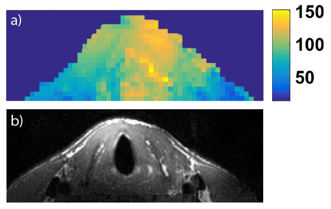
Figure 5a shows the B1-map obtained after RF shimming in the ROI. An excitation flip angle of 90-120% obtained after which TSE imaging was performed. The MR image (Figure 5b) shows a good coverage up to and including the posterior side of the larynx and no movement artefacts are visible. Comparing to 3T images1 we observe that same image quality can be obtained with 0.5 mm3 voxels at 7T instead of 1.0 mm3 voxels at 3T in only 6 seconds per slice for a 2D acquisition.
Conclusion and Discussion
Although dedicated transceive coils for carotid artery imaging at 7T exist, this is to our knowledge the first example of a transceiver array designed specifically for laryngeal imaging. The combination of 5 shielded loops and 3 passively fed dipoles showed high inter-element isolation (greater than -19 dB), enabling RF shimming to be performed over the larynx, and to obtain good image uniformity even when using TSE sequences.Acknowledgements
This work was funded by NWO grant #13783 and ERC NOMA-MRI 670629References
- Ruytenberg, T., Verbist, B. M., Oosten, V. V., Astreinidou, E., Sjögren, E. V., & Webb, A. G. (2018). Improvements in High Resolution Laryngeal Magnetic Resonance Imaging for Preoperative Transoral Laser Microsurgery and Radiotherapy Considerations in Early Lesions. Frontiers in oncology, 8, 216. 2.
- King, R.W.P., Mimno, H.R., Wing, A.H. (1945) Transmission lines, Antennas and Wave Guides, New York: McGraw-Hill Book Company Inc.
- Zivkovic I. , O’Reilly T., Brink W., Webb A. (2018) Design of a passive feed network to increase the transmit efficiency of dipoles at 7T. Joint Annual Meeting ISMRM-ESMRMB 2018, Paris, France. Proc ISMRM #4434
- Ertürk, M. A., Raaijmakers, A. J., Adriany, G., Uğurbil, K., & Metzger, G. J. (2017). A 16‐channel combined loop‐dipole transceiver array for 7 Tesla body MRI. Magnetic resonance in medicine, 77(2), 884-894.
Figures