1527
Optimization of small animal RF coil with co-simulation approach1Institute of Imaging Science, Vanderbilt University, Nashville, TN, United States, 2Radiology and Radiological Science, Vanderbilt University, Nashville, TN, United States
Synopsis
The 3D electromagnetic and RF circuit co-simulation approach is a fast and accurate tool to calculate the EM fields of RF coils. It is typically used for human coils to evaluate the transmit field and SAR. In this work, we apply this method to the circuit optimization of a small animal coil. Unlike human coils, the coil noise of small animal coil is not neglectable and should be minimized. With the guide of co-simulation approach, an optimized saddle-shaped surface coil has considerable transmit efficiency and SNR improvement on ex-vivo squirrel monkey brain imaging at 9.4T.
Introduction
Numerical simulation is an invaluable tool to understand and aid the design of RF coils 1-3. A straightforward and accurate approach is to solve Maxwell’s equations with a 3D full-wave electromagnetic simulation. However, this requires a lot of time and is not practical for designers to perform complex RF circuit optimization. The co-simulation method 4 provides a bridge between a time-consuming EM simulation and efficient RF optimization. It has been widely used for human coil design to evaluate the RF field and SAR, but has not apparently been used for coil designs for small animals where the coil noise is not neglectable and the matching circuit and antenna effect have to be properly considered. Here we evaluated the co-simulation approach to develop improved coils for use on small animal systems at 9.4T.Methods
Co-simulation setup4
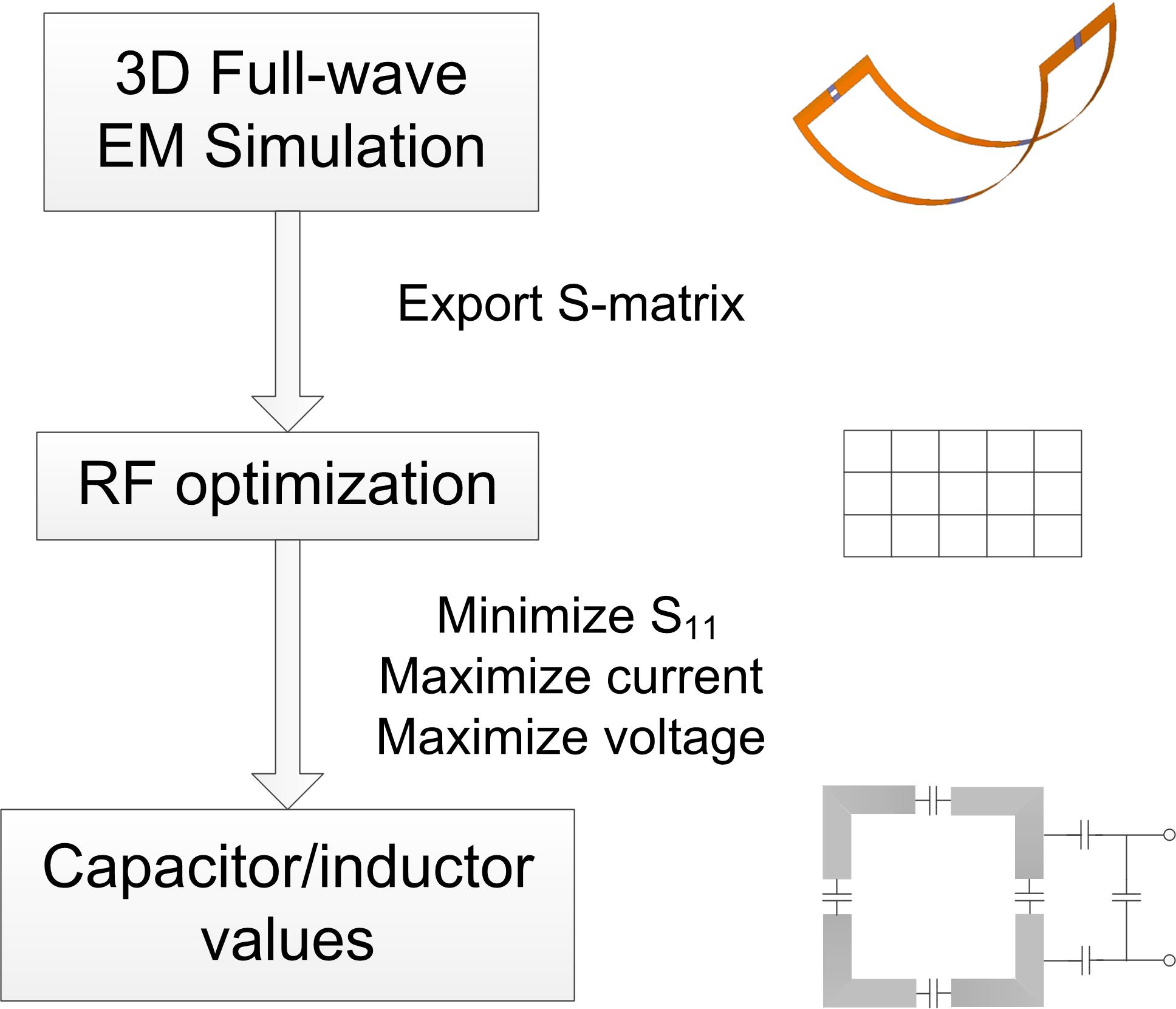
First, a saddle-shaped RF surface coil was modeled using the full-wave electromagnetic (EM) solver with Finite-Element Method (Ansys HFSS, Canonsburg, PA, USA). All conductors were modeled as real 3-D structures (copper, 35-um-thickness) rather than ideal conductors without ohmic loss. We observed that the conductors’ inductance is approximate 5% smaller than the practical case if they are modeled as 2D copper sheets. Lump elements including capacitors and inductors were replaced with 50-ohm-ports. Then, the scatting (S-) matrix was obtained in a relevant frequency range and exported into home-built MATLAB code (The MathWorks, Inc, Natick, MA, USA) for RF circuit optimization. Note that this S-matrix includes the self- and mutual- impedances among different conductors and mutual coupling between the coil and the loading. In the RF circuit modeling, the lump elements were optimized to maximize the current along the conductor as well as to maintain perfect tuning/matching performances (S11<-30 dB), as shown in Figure 1. Note that RF circuit optimization can also be performed with commercial circuit simulators, such as Agilent ADS, SPICE and Ansys Designer.
Bench tests and MR Experiments
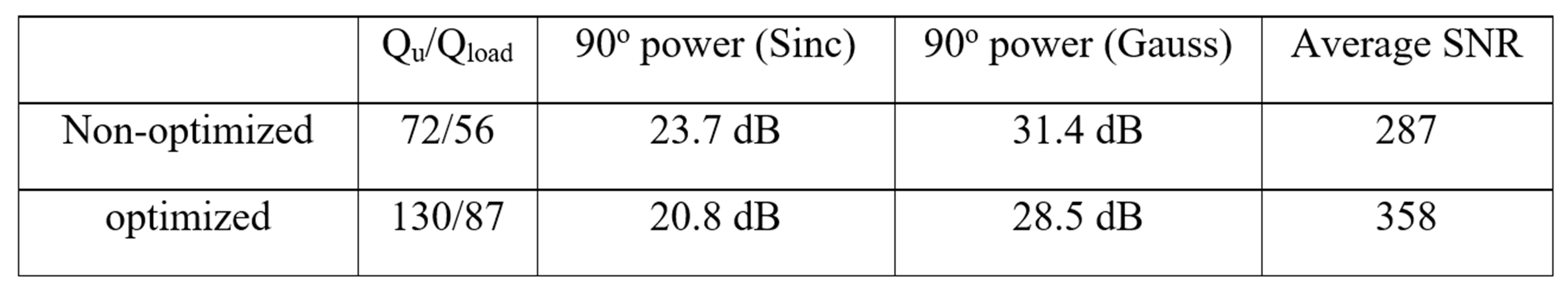
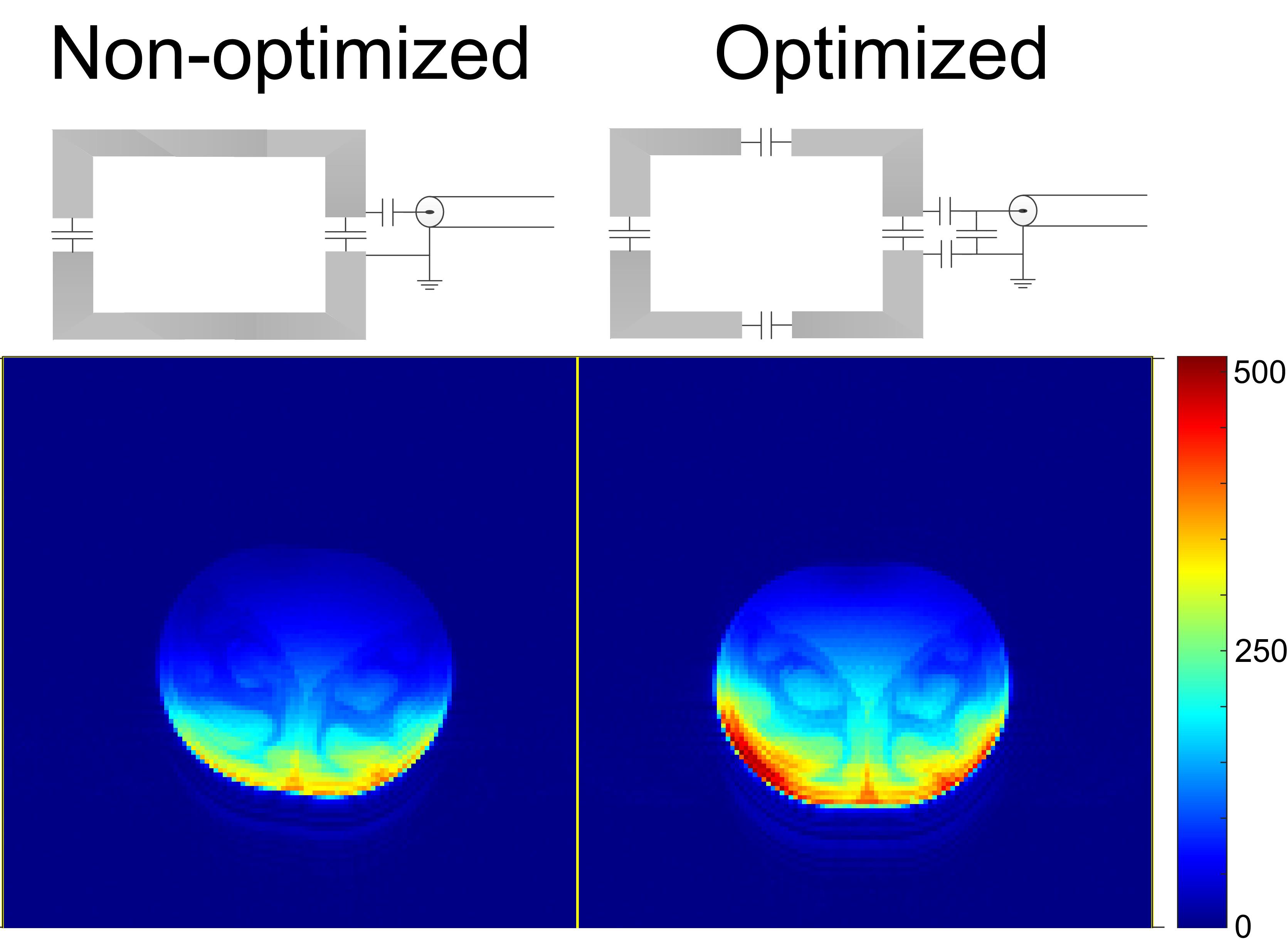
The co-simulation approach was validated on a saddle-shape loop coil designed for imaging squirrel monkeys at 9.4 T. A non-optimized coil with one distributed capacitor and an unbalanced capacitive matching circuit was used for baseline comparisons. For the same input power, the optimized coil has 31% stronger current along the conductors and almost double the unloaded quality (Q-) factor. To validate simulation results, the same coils were then built and validated in bench measurements and MR experiments using a 9.4 T Varian small animal scanner (12-cm-diameter bore within the gradients). Float trap circuits are used for both coils to suppress the common mode current.
MR images were acquired of an ex-vivo brain. The required RF power to achieve a 90 degree pulse was calibrated by increasing the RF power step by step with the same RF pulse. Both slice-selective (Sinc) and non-slice-selective (Gauss) pulses were used for calibration. For the slice selective pulse, the power was calibrated on a coronal plane which is 1cm away from the bottom. Low flip angle GRE images with the following parameters were acquired for SNR calculation: TR/TE=2000/2.76 ms, flip angle =35o, bandwidth=390.6 Hz/pixel, slice thickness=1mm and in-plane resolution =0.5x0.5mm2.
Results
In practical coil fabrication, the capacitance values used have less than 5% deviation (measured with Agilent LRC meter) compared to simulated values. Table 1 shows the measured Q-factor, power calibration results and average SNR. The SNR was calculated by SI/mean(noise), where SI is the signal intensity of the GRE images and mean (noise) is the average noise in background areas. Figure 2 shows the SNR map in the central transverse slice. In either non-selective and selective cases, the required RF power to achieve 90 degree of the optimized coil is 2.9 dB lower than that of the non-optimized coil, indicating ~48% transmit efficiency improvement by using the optimized coil. Notable overall SNR improvement was observed (24.8%), which is also consistent with the simulation results. We believe the transmit efficiency and SNR increases are from improvements in the balanced matching, segmented capacitor distribution, and setting the virtual ground at the coil center1-3. In this work, we did not calculate the magnetic or electric field distributions in the EM simulation software. However, this can be easily done by using the capacitance/inductance derived from the RF circuit optimization.Conclusion
A co-simulation approach can accurately predict each lump element's value and optimize the capacitance distribution and matching network to minimize coil losses. The co-simulation approach is thus a useful tool for small animal coil designs, and also an aid for understanding the behaviors of RF coils better.Acknowledgements
No acknowledgement found.References
1. Giovannetti, G., Landini, L., Santarelli, M.F. et al. MAGMA (2002) 15: 36.
2. Doty, F. David, et al. "Radio frequency coil technology for small‐animal MRI." NMR in Biomedicine: An International Journal Devoted to the Development and Application of Magnetic Resonance In vivo 20.3 (2007): 304-325.
3. Mispelter J. l., Lupu M. & Briguet A. NMR Probeheads for Biophysical and Biomedical Experiments: Theoretical Principles & Practical Guidelines Imperial College Press, Distributed by World Scientific (2006).
4. Kozlov, Mikhail, and Robert Turner. "Fast MRI coil analysis based on 3-D electromagnetic and RF circuit co-simulation." Journal of magnetic resonance 200.1 (2009): 147-152.
Figures