1525
A 64-Channel Phased-Array Head Neck Coil for Neurovascular/fMRI at 3T1Quality Electrodynamics, LLC (QED), Mayfield Village, OH, United States, 2Canon Medical Research USA, Inc., Mayfield Village, OH, United States, 3Canon Medical Systems Corporation, Kanagawa, Japan
Synopsis
Close-fitting the coil elements along the head and neck is a typical design of higher density phased-array head neck coils in order to provide higher SNR and acceleration. But this limits patient comfort and excludes larger patients. In this work we present a 64-channel head neck coil which can image large patients for neurovascular/fMRI at 3T. The coil test results show superior SNR in imaging compared to both a clinical 32-channel head array coil and 16-channel head neck array coil respectively.
Introduction
Higher density phased-array coils with higher SNR are becoming increasingly popular in clinical neurovascular assessment and fMRI imaging. This application requires large FOV at head/neck area and higher acceleration with superior SNR. A 32-channel brain coil provides good images for brain and fMRI but lacks coverage over the C-spine. The performance of a 16-channel head neck coil demonstrates excellent C-spine images but it is not suitable for the application of highly accelerated imaging. A 64-channel phased-array coil as previously reported1 provides both highly accelerated imaging of the brain and neck with improved SNR, but the close-fitting elements design had poor patient comfort and limited the use case for fitting a variety of patient sizes. Here, we present a 64-channel head neck prototype coil which allows the imaging of large patients up to 99th percentile US male for neurovascular and fMRI imaging at 3T. The performance of this coil shows higher SNR compared to both a clinical 32-channel head array coil and a 16-channel head neck array coil in brain and C-spine regions respectively.Methods
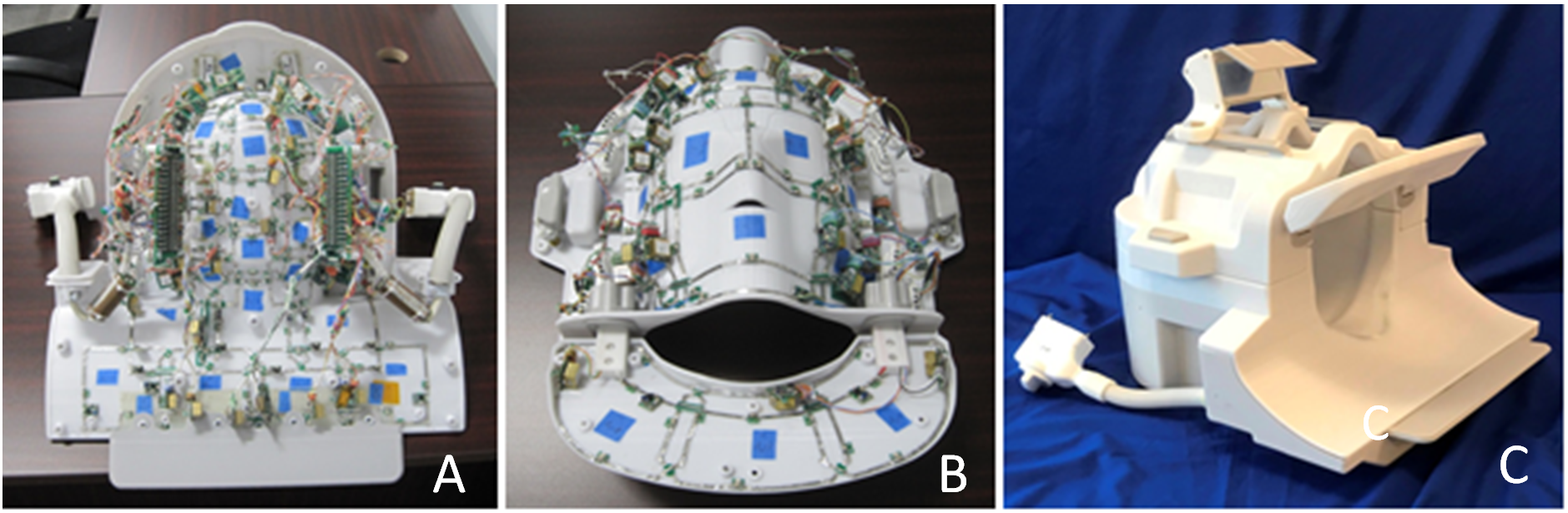
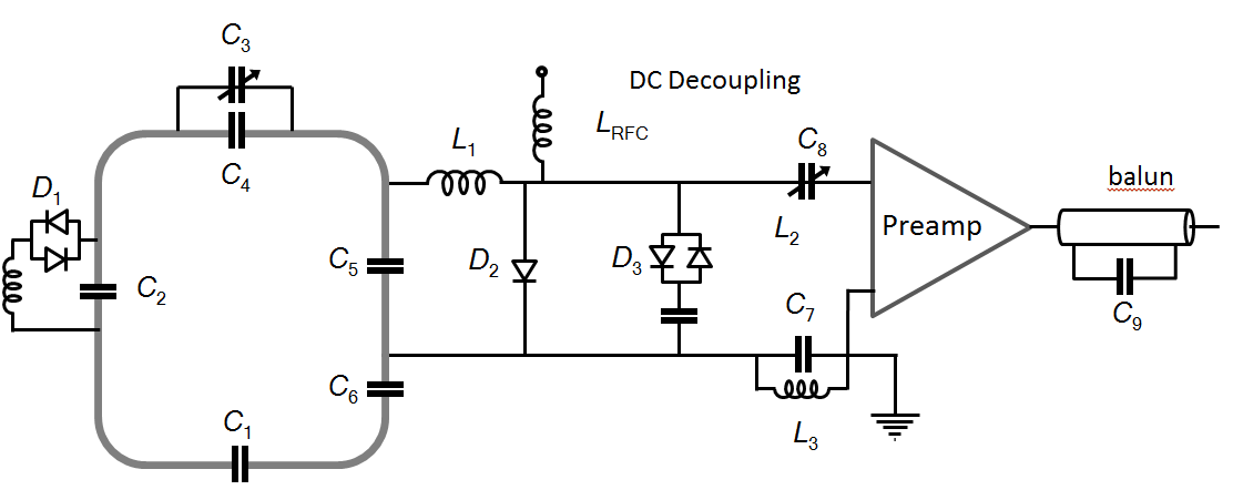
The coil size and shape were optimized for fitting 99th percentile US male as shown in Fig.1. The head portion inner surface size: 205 mm Left-Right (L-R), 243 mm Anterior-Posterior (A-P) and 262mm Head-Foot (H-F). Including the neck portion, the total coil size is 460 mm H-F. The housing prototype was 3D printed using a Fortus 900mc printer. The array coil comprises 42 elements on the posterior part and 22 elements on the anterior. The anterior has a movable portion, which can be adjusted up or down (4 elements) for optimizing C-spine imaging according to different sized patients. Three switchable modes (Brain, C-spine and neurovascular mode) allow user to scan the brain with 50 elements, C-spine with 32 elements and neurovascular with 64 elements. The coil also can fit the ACR phantom for MRI system QA. Loops between the eyes and mouth are decoupled using shared capacitive decoupling method which maximizes the opening windows on anterior part. The adjacent loops between anterior and posterior were geometrically decoupled by partially mechanical overlap of the split posterior and anterior housing design. Seven columns were built on posterior and five on anterior along L-R direction at brain ROI. Each column consists of at least 4 elements (H-F direction) except eyes and mouth area. This design assures the coil can be run for reduction factor of R=2, 3 and 4. Coil element sizes are optimized based on overall coil former size, coil QUnloaded/QLoaded ratio and total number of coil elements 2, 3. The typical element size is 75mm X 80mm for brain and 110mm X120mm for C-spine. The copper width for each element is 2.5mm and the schematic circuit is shown in Fig.2. The size of feed board which is integrated with active/passive decoupling, preamplifier decoupling and output balun circuit was minimized. All feed boards and cable arrangements, including locations and orientations, were optimized in such a way that RF shield effect and coupling between coil elements through cables were minimized and higher QUnloaded/QLoaded ratio of each element was achieved. The coil was tuned at 123.2 MHz and image data were acquired on a Vantage Titan 3T system (Canon Medical Systems, Otawara Japan), with a conductive head neck phantom made of PVA (Polyvinyl Alcohol) and in normal subjects (5 volunteers include a 350 pound male) then analyzed for regional SNR and qualitative comparison.Results
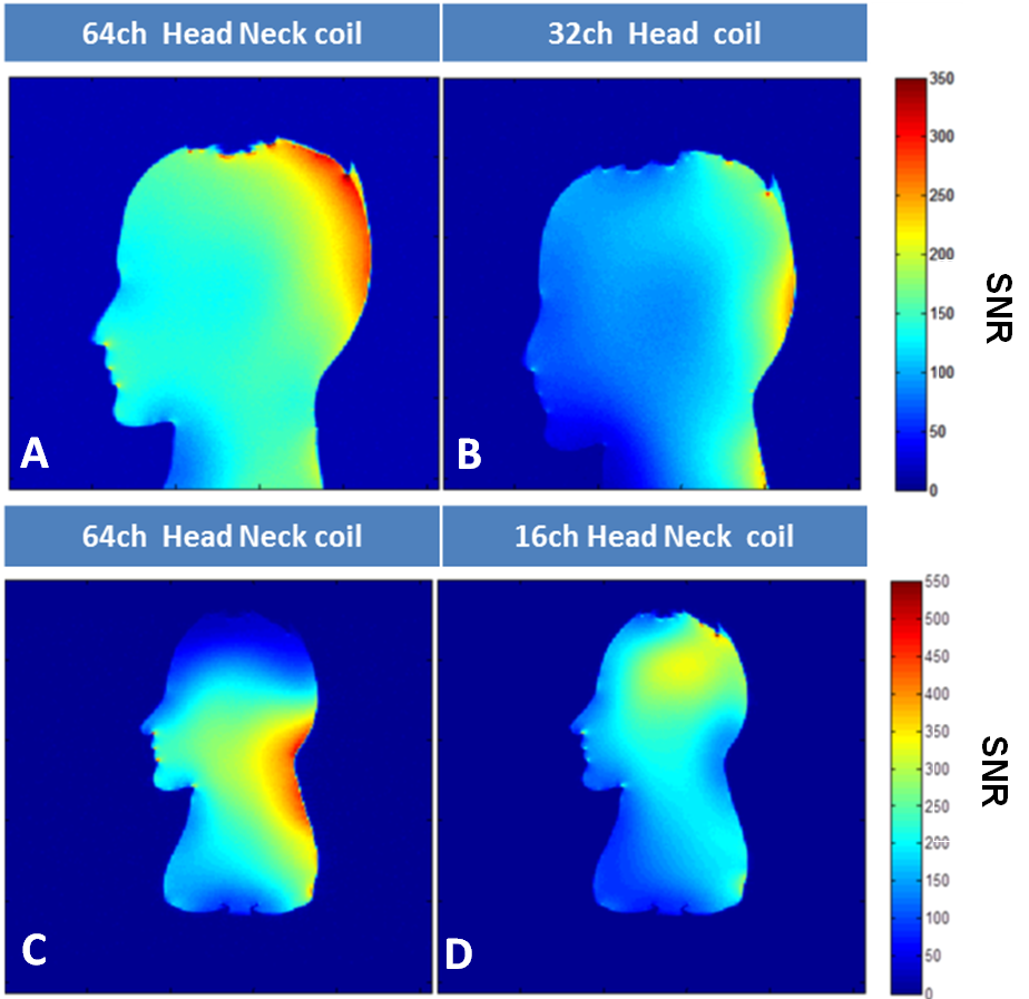
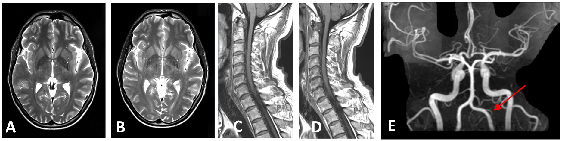
Typical coil element QUnloaded/QLoaded ratio for the receive coils was 200/48=4.1. The 64-channel head neck coil showed that the SNR increased 45% at the locations of the brain cortex and center compared to clinical 32-channel head coil and more than 50% in the ROI of C-spine compared to a clinical 16-channel head neck coil respectively for phantom imaging. The detail of comparison SNR map is as shown in Fig3. Volunteer images acquired with 64-channel array coil are shown in Fig4.Discussions and Conclusions
The large aperture 64-channel head neck coil fits 99th percentile US male and increase patient comfort. This coil improves image SNR in both brain and C-spine compared to a clinically-available 32-channel head coil and a 16-channel head neck coil respectively.Acknowledgements
The authors thank John Pitts2 for clinical evaluation and providing volunteer images.References
1. B. Keil et al. A 64-Channel Array Coil for 3T Head/Neck/C-spine Imaging, Proc. Intl. Soc. Mag. Reson. Med. 19 (2011)
2. W. A. EDELSTEIN et al, MAGNETIC RESONANCE IN MEDICINE 3,604-6 I8 (1986)
3. Steven M. Wright and Lawrence L. Wald, NMR IN BIOMEDICINE, VOL. 10, 394–410 (1997)
Figures