1519
Design Considerations of a 64-Channel Receive / 16-Channel Transmit Coil Array for Head, Neck, and Cervical-Spine Imaging at 7 TMarkus May1, Robin Etzel1, Laleh Golestanirad2, Christina Triantafyllou3, Yulin V. Chang4, Shivraman Giri4, Lawrence L. Wald5, and Boris Keil1
1Institute of Medical Physics and Radiation Protection, Dep. of Life Science Engineering, Mittelhessen University of Applied Science, Giessen, Germany, 2Department of Radiology, Northwestern University, Chicago, IL, United States, 3Siemens Healthineers AG, Erlangen, Germany, 4Siemens Medical Solutions USA, Inc., Boston, MA, United States, 5A.A. Martinos Center for Biomedical Imaging, Dept of Radiology, Massachusetts General Hospital, Harvard Medical School, Boston, MA, United States
Synopsis
A 64chRx/16chTx head-neck-Cspine array coil was constructed and bench tested. A new UHF topology has been introduced, by merging two commonly separated array coil functionalities (Rx, Tx) at ultra-high field MRI into one anatomically shaped close-fitting housing. The ultimate two-folded goal of this study was to increase clinical benefit in ultra-high field neuroimaging through the extension of the brain region to the cervical spine and to decrease patient’s anxiety and discomfort using a patient-friendly coil design.
Introduction
There is growing interest in combined head and neck imaging at ultra-high-field MRI for assessing a variety of neurodegenerative diseases [1,2] or to gain a deeper understanding of the neural orchestration of the cervical and cerebro-cerebellar circuitries [3,4]. At ultra-high fields, however, the difficulty of constructing highly parallel coils arrays and the lack of commercial coils has limited head-neck imaging for research and clinical studies. When both parallel transmit and high-density receive arrays are employed, the Tx and Rx functionality is usually separated into two housing segments: (i) a close-fitting head former for the receivers and (ii) an external sliding tubular ring structure, which comprises the Tx elements [4-6]. The latter is pulled over the subject’s head, which often triggers anxieties and substantial discomfort [7]. In this study, we changed the commonly used coil topology for UHF head Tx/Rx array coils, where we merged the Rx and Tx structure into one anatomical-shaped close-fitting housing design (Fig.1), without the need of the external cylindrical Tx housing. Here, we show preliminary results in coil construction and bench measurements of a newly engineered 64chRx/16chTx densely packed head-neck coil for 7T MRI.Methods
The array coil was designed on an anatomically shaped former and comprises two parts: a large posterior head-neck section with 40 Rx elements (Fig.3), and an anterior head-neck portion with 24 Rx elements (Fig.2). After implementing all Rx loops, a 3D-printed rail system was mounted on top of the Rx array structure, where 16 Tx coils were placed. Rx coil adjacent preamplifiers were placed directly in-between the Tx/Rx structure (see Fig.4). Hence, both the Rx and Tx coil structures closely follow the natural morphology of the head and neck. Large cut-outs for eyes and mouth facilitate visual stimulation and free breathing, respectively. Beyond the regular coil covers, no further external housing parts are needed anymore, which are commonly used to accommodate the UHF Tx coils. All helmet parts including its covers were printed in polycarbonate plastic using a rapid prototyping 3D printer (Fortus 350, Stratasys, Eden Prairie, USA). The conductive structures of all coil elements were constructed using semi-flexible circuit board material. For the Rx loop layout, a mixture of shared conductor design and critical overlap was employed for geometrically decoupling adjacent loop pairs. Next-nearest neighboring Rx elements were decoupled using preamplifier decoupling [8]. The matching network, the active detuning circuitry, and the passive coil detuning were placed on the preamplifier’s daughter board. Tx coil decoupling of nearest neighboring elements was implemented using a mutual inductance concept [9]. Different offset distances between the merged Rx and Tx coil structure were evaluated for coil-to-coil interactions. So far, we have evaluated the 64chRx/16chTx array coil with bench-level measures of element performance and decoupling.Results
When separating the Rx and Tx element layers by an offset of 1.5cm, the Rx coil to Tx coil interactions were negligible small. Smaller offsets (<1cm) caused substantial increased interaction between the transmit and receive elements, where the unloaded Q of the Rx loops were degraded by up to 17%. Bench tests for the Rx array showed an average geometrical decoupling of 16dB. The coupling between next-nearest neighbors (non-adjacent pairs) ranged from 14dB to 26dB. An additional isolation of 18dB was achieved from preamplifier decoupling. Active PIN diode detuning provided >43dB isolation between the tuned and detuned states. For the Tx loops, we optimized the coupling of adjected loops to -20dB by empirically changing the mutual decoupling inductance. Decoupling between non-adjacent Tx loop pairs showed an isolation of >23dB, thus no further decoupling networks were needed.Discussion
Combining highly parallel detection and parallel transmit inside the small space of a close-fitting anatomical head-neck housing at 7T presents many technical challenges. We found, when maintaining an offset of ~1.5cm between Rx and Tx element layers, the inter-coil coupling was small (only 4% decrease of unloaded Q). Smaller distances, however, caused substantially increased interaction between the Rx and Tx structures. Both coil layers were controllable on the bench for needed tuning and matching adjustments.Conclusion
A 64chRx/16chTx head-neck-Cspine array coil was constructed and bench tested. A new UHF topology has been introduced, by merging two commonly separated array coil functionalities (Rx, Tx) at UHF into one anatomically shaped close-fitting housing. This yielded to an overall lower housing profile without any additional obstructive parts over eyes and mouth. Our preliminary results show promising potential for increased clinical benefit in UHF neuroimaging through the extension of the brain region to the cervical spine, while we decrease patient’s anxiety and discomfort using a more patient-friendly UHF coil design.Acknowledgements
Partially funded by BMBF Grant # IN2016-2-226References
[1] Katdare A, Ursekar M.Ann Indian Systematic imaging review: Multiple Sclerosis. Acad Neurol. 2015,18(Suppl 1):S24-9. [2] Wright D, Martin S, Pereira EA, Kong Y, Tracey I, Cadoux-Hudson T. High field structural MRI in the management of degenerative cervical myelopathy. Br J Neurosurg. 2018, 24:1-4. [3] Stoodley CJ, Valera EM, Schmahmann JD. Functional topography of the cerebellum for motor and cognitive tasks: an fMRI study. Neuro- Image 2012;59:1560–1570. [4] Kueper M, Thuerling M, Stefanescu R, et al. Evidence for a motor somatotopy in the cerebellar dentate nucleus—An FMRI study in humans. Hum Brain Mapp 2012;33:2741–2749. [4] Ledden PJ, Mareyam A, Wang S, an Gelderen P, Duyn J, 32-Channel receive-only SENSE array for brain imaging at 7 T, in: Proceedings of the 15th Annual Meeting of ISMRM, Berlin, 2007, p.242. [5] Keil B, Triantafyllou C, Hamm M, Wald LL. Design optimization of a 32- channel head coil at 7 T, in: Proceedings of the 18th Annual Meeting of ISMRM, Stockholm, 2010, p.1493. [6] Shajan G, Kozlov M, Hoffmann J, Turner R, Scheffler K, Pohmann R. A 16-channel dual-row transmit array in combination with a 31-element receive array for human brain imaging at 9.4 T. Magn Reson Med. 2014,71(2):870-9 [7]van Osch, M.J.P. & Webb, A.G. Curr Radiol Rep (2014) 2: 61. [8] Roemer PB, Edelstein WA, Hayes CE, Souza SP, Mueller OM. The NMR phased array, Magn Reson Med 16 (1990) 192–225. [9] Wu B, Qu P, Wang C, Yuan J, Shen GX. Interconnecting L/C components for decoupling and its application to low-field open MRI array, Concepts Magn Reson Part B Magn Reson Eng 31B (2007) 116–126.Figures
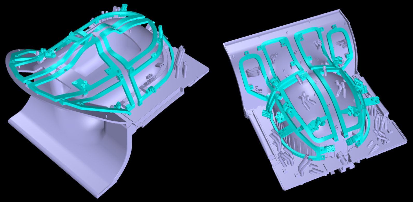
Figure 1: 3D Model of the constructed 64chRx/16chTx
head-neck 7T coil array. The rail structure (green) is the mounting rack for
the 16ch Tx elements and follows the anatomical shape of the 64ch Rx coil
former.
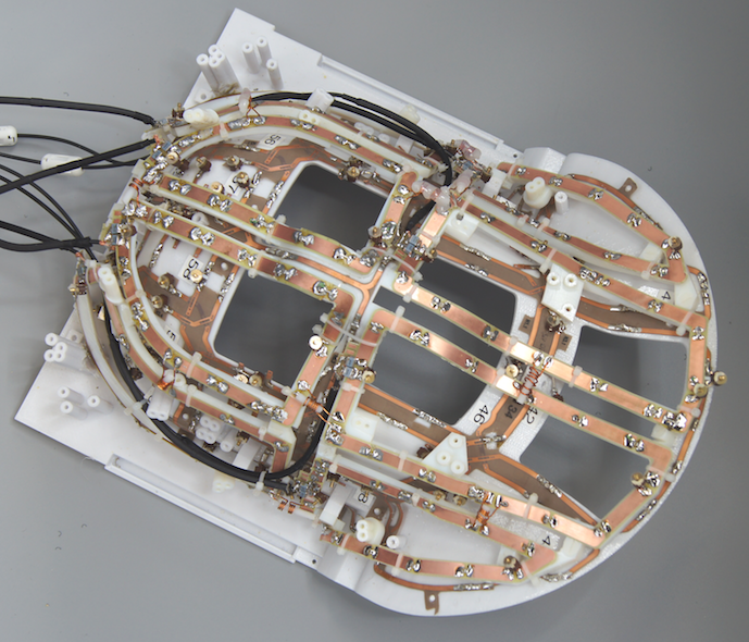
Figure 2: Anterior segment of the 64chRx/16chTx head-neck coil that comprises 24 receive loops and 8 transmit loop elements.
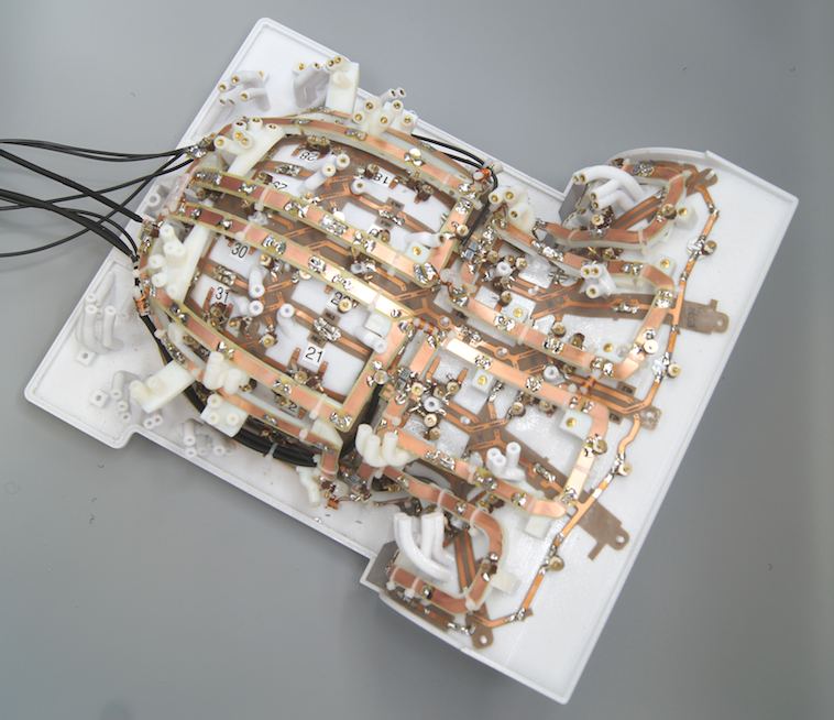
Figure 3: Posterior segment of the 64chRx/16chTx head-neck coil that comprises 40 receive loops and 8 transmit loop elements.
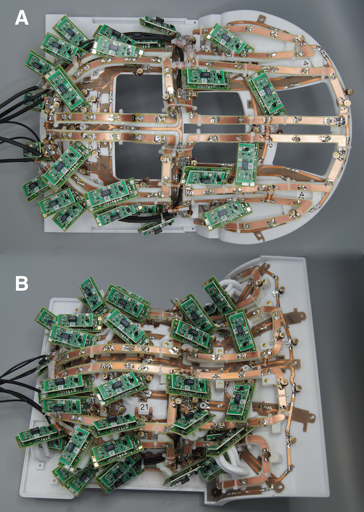
Figure 4: Assembled anterior (A) and posterior (B) part of the 64chRx/16chTx head-neck coil with preamplifiers.