1518
Dependence of Radiofrequency field enhancement on the geometry of the monolithic high dielectric ceramics at 3 T1Radiology, The Pennsylvania State University College of Medicine, Hershey, PA, United States
Synopsis
Ultra-high dielectric constant (
Purpose
In recent years, ultra-high dielectric materials have been shown as strong passive RF field manipulator or local field enhancer for MRI [1,2]. For effective utilization of dielectric materials specifically in MRI experiments, the optimal geometry and dielectric-coil configuration are of great interest. For a specific geometry and dimension, the uHDC ceramics can produce its intrinsic resonance modes [3]. This study investigated geometric dependence of RF field in a phantom on the geometries and dimensions of coil and dielectric ceramic blocks, by comparing different dielectric-coil setup with different dielectric thickness, coil size and resonance conditions.Methods
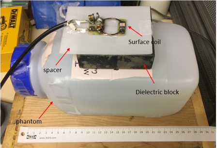
The uHDC material used in this study is Lead Ziroconate Titanate, (HyQ Research Solutions, State College, PA). It has relative permittivity of 1000 and loss tangent of 0.04 at 3 T. Two rectangular uHDC blocks are used in this study. One is 109 mm x 86 mm x 26 mm and the other one is 90 mm x 86mm x 26 mm. Three different sized coils (large: 86 cm x 86 cm, medium: 61 cm x 61 cm, small loop coil: radius=15 mm) are used to couple with the uHDC blocks. The simulation setup is shown in Figure 1, and the two different blocks and three different surface coils are shown in Figure 2. The experimental setup is shown in Figure 3. The resonance condition is determined by measuring the frequency response (S11) of the coil-dielectric-phantom system in the simulation. All the coil-dielectric configurations are simulated with computer modeling and tested in experiments. Simulated B1+ results are normalized by the power dissipated into the phantom to show the transmit efficiency. In experiments, all coils are tuned to the 3T frequency and have similar coupling condition (-30 dB). B1+ map is captured from experiments. The thickness effect of the uHDC material is simulated in XFdtd. The simulation setup is similar to Figure 1. The square coil used in the simulation is 66 mm x 66 mm, and the uHDC material thickness is varied from 10 mm to 26 mm with a 1 mm step. The effect of uHDC material thickness is studied by calculating the normalized total magnetic flux from the coil into the phantom, which is the total net flux divided by the power dissipated into the phantom. This is a good indicator of the coupling efficiency between the coil and phantom, where a good coupling would eventually enhance the B1+ field in the phantom.Result and Discussion
Figure 4 shows the six representative RF coil-dielectric configurations used for this0 study. The simulated and experimental transmit efficiency maps for all six different setups are in good agreement as shown in Figure 5. The plot of normalized net flux into the sample from the HDC blocks as a function of thickness is shown in Figure 6. Examining Figure 4, for the short block, the response of all 3 configurations are very close to on-resonance condition. On the other hand, the resonance condition varies greatly for the long block, where the small coil is close to resonance but other two coil conditions are off-resonance. When relating the resonance condition to the transmit efficiency map, we can observe that when the configuration is on or close to resonance, stronger enhancement can be achieved in transmit efficiency. Another observation is larger coil will also introduce more enhancement to the transmit efficiency.
Thicker dielectric blocks have more dielectric material and can generate stronger RF field, but also would introduce more loss to the system, and move the coil further away from the phantom. By examining Figure 5, we observe that for a given dielectric block geometry, there is an optimized thickness for best coupling between the coil and the phantom sample. The maximum coupling efficiency appears at 18 mm thickness and 21 mm thickness for the long block and short block respectively.
Conclusion
Our simulated and experimental data show that large coils have stronger enhancement when incorporated with dielectric blocks with its intrinsic resonance fundamental mode coincide the resonance condition. For each specific rectangular dielectric block, there is an optimal thickness of the material that produces most coupling between the coil and phantom sample.Acknowledgements
No acknowledgement found.References
[1] Yang, Qing X., et al. "Manipulation of image intensity distribution at 7.0 T: passive RF shimming and focusing with dielectric materials." Journal of Magnetic Resonance Imaging: An Official Journal of the International Society for Magnetic Resonance in Medicine 24.1 (2006): 197-202.
[2] Rupprecht, Sebastian, et al. "Improvements of transmit efficiency and receive sensitivity with ultrahigh dielectric constant (uHDC) ceramics at 1.5 T and 3 T." Magnetic resonance in medicine 79.5 (2018): 2842-2851.
[3] Aussenhofer, S. A., and A. G. Webb. "High‐permittivity solid ceramic resonators for high‐field human MRI." NMR in Biomedicine 26.11 (2013): 155 5-1561.
Figures