1516
Flexible Low-Profile Coil Array Using “Dummy Loads” for Concurrent TMS-fMRIWilliam Mathieu1 and Reza Farivar2
1Electrical and Computer Engineering, McGill University, Montreal, QC, Canada, 2Ophthalmology, McGill University, Montreal, QC, Canada
Synopsis
A system was designed for concurrent TMS-fMRI, where functional images across the entire brain may be acquired while stimulating areas with TMS. Dummy loads were used to counteract the loading effects of the TMS coil. This system was able to perform functional acquisitions on phantoms and biological media with the TMS coil present.
Introduction
Concurrent TMS-fMRI studies are often constrained by the available positions for the TMS coil due to the limited space inside an MR scanner. Furthermore, TMS coils often load RF coils, which negatively affects their tuning and matching. Bulky RF coil housings are the main contributor to the space limitation and may prevent access to entire regions of the brain. For example, in studies investigating visual processes, a subject must lie on their back to visualize stimulus, making TMS stimulation of visual regions impossible with conventional RF coils. Previously, a small 8-channel array was connected to a TMS coil to allow imaging of only stimulated regions.1 Our design allows for imaging of the entire brain volume without limiting TMS coil positioning. Flexible, low-profile RF coils were constructed which warp around a subject’s head, a subject is positioned on a purpose-built patient table which allows for both prone and supine positioning, while the TMS coil may be positioned to target any brain area. A novel method for counteracting the loading effects of the TMS coil on the RF coil was developed: the RF coils are loaded with a wire loop, “dummy load” (DL), having the same loading effects as the TMS coil. The RF coil is tuned and matched while loaded with either the dummy load or the TMS coil, when the TMS is not in the vicinity of the RF coil a dummy load is placed in its stead ensuring the RF coil’s behavior remains unchanged, see Figure 1.Methods
A three channel array was constructed using flexible copper clad polyimide in the loop segmented by four capacitors, one of which was variable. A matching network and detuning diode were also included. A circuit diagram of a single coil is shown in Figure 2c. Coil tuning and matching were done with a 2-port VNA (Copper Mountain Technologies, Indianapolis, USA). Experiments were run on a 3T clinical MR scanner (Prisma, Siemens Healthcare, Erlangen, Germany). Anatomical images were acquired to study best case SNR using an MPRAGE sequence with parameters: TE=2.98 ms, TR=2300 ms, FoV=256×256×176 mm3, BW=240 Hz/Pixel, and α=9⁰. Functional images were acquired using a BOLD sequence with parameters: TE=30 ms, TR=2940 ms, FoV=192×192×75 mm3, BW=1736 Hz/Pixel, α=60⁰, and 300 measurements. The coil array was placed on a standard bottle phantom on the scanner’s patient bed. An MR-compatible TMS coil (MRi-B91 coil, MagVenture, Farum, Denmark) was placed tangential to the cylinder of the bottle phantom, pressed up against the coil array. Anatomical acquisitions were performed for different TMS coil positions, with the dummy loads present or absent.Results and Discussion
Figure 3 shows SNR calculated along coronal slices for two coils. the first row of slices corresponds to coil 1 being the conventional design, the second row corresponds to coil 2 which employs a “dummy load”. Four conditions (columns) were tested across two coils: (i) no TMS coil present and a DL on coil 2, (ii) no TMS coil present and no DL present on coil 2, (iii) TMS coil and DL placed on coil 2, and (iv) TMS coil on coil 2 and no DL. Coil 2 provides slightly higher SNR values compared to coil 1. Furthermore, the DL appears to stabilize SNR across conditions when the TMS is present or absent. Figure 4 shows anatomical images of a pineapple, the TMS was not present. The conventional coil (a) exhibits lower SNR compared to coil (b) which uses a DL. Figure 5 shows a single BOLD measurement computed from the combined signal from coils 1 and 2.Conclusion
This system provides a way for the near-simultaneous induction and registration of brain activity across the entire brain volume. Dummy loads simplify the technical limitations of concurrent TMS-fMRI by improving the stability and performance of thin flexible coil arrays.Acknowledgements
No acknowledgement found.References
1. Navarro de Lara, L.I., et al. A novel coil array for combined TMS/fMRI experiments at 3 T. Magnetic resonance in medicine 74, 1492-1501 (2015).Figures
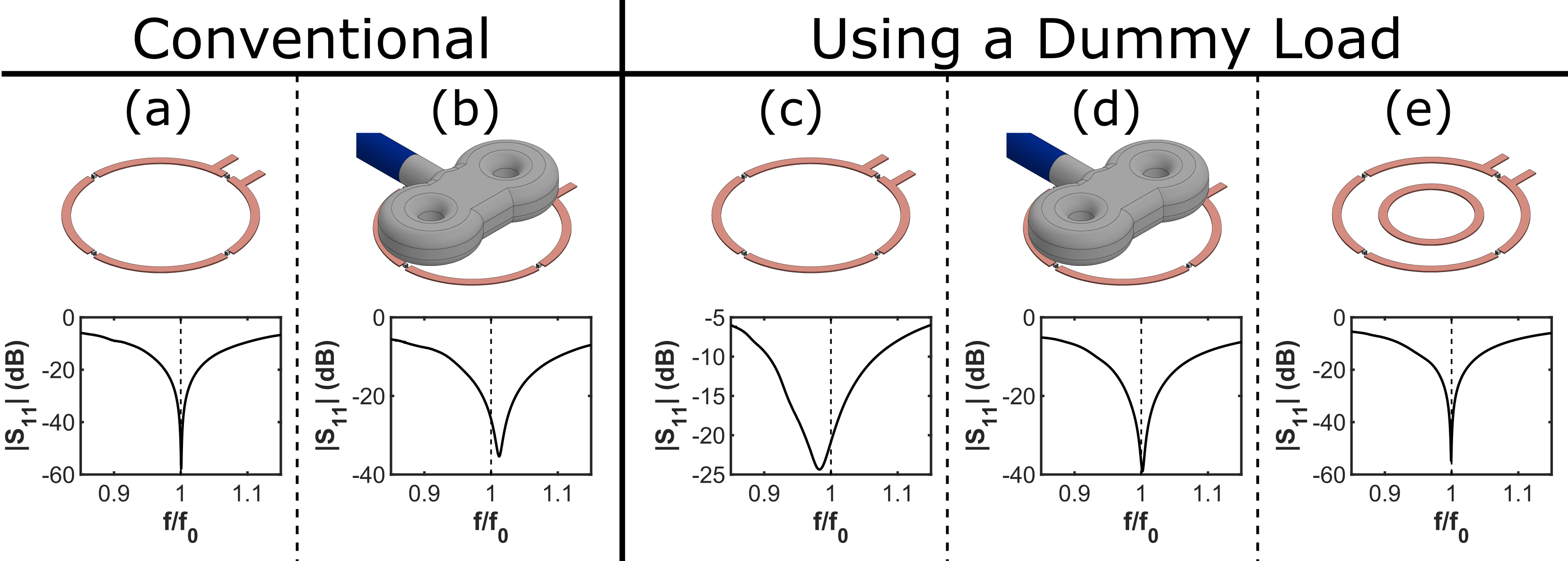
Figure 1: Conventional RF coil (a) resonating at Larmor
frequency. (b) Loading of TMS coil causes the RF coil to resonant at a higher
frequency. (c) Tuning RF coil to a low resonant frequency, (d) therefore when
loaded with a TMS coil the resonance of the RF coil increases to the correct frequency.
(e) When not loaded with TMS coil a “dummy load” is used to maintain resonance
at the correct frequency.
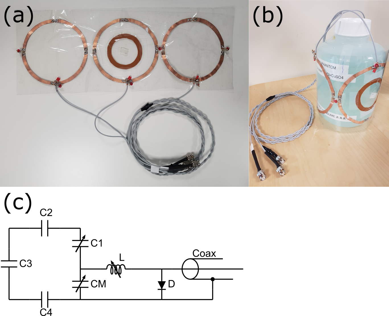
Figure 2: (a)
Three element flexible, low-profile array. (b) Array wrapped around bottle phantom.
(c) Circuit diagram of a single coil.
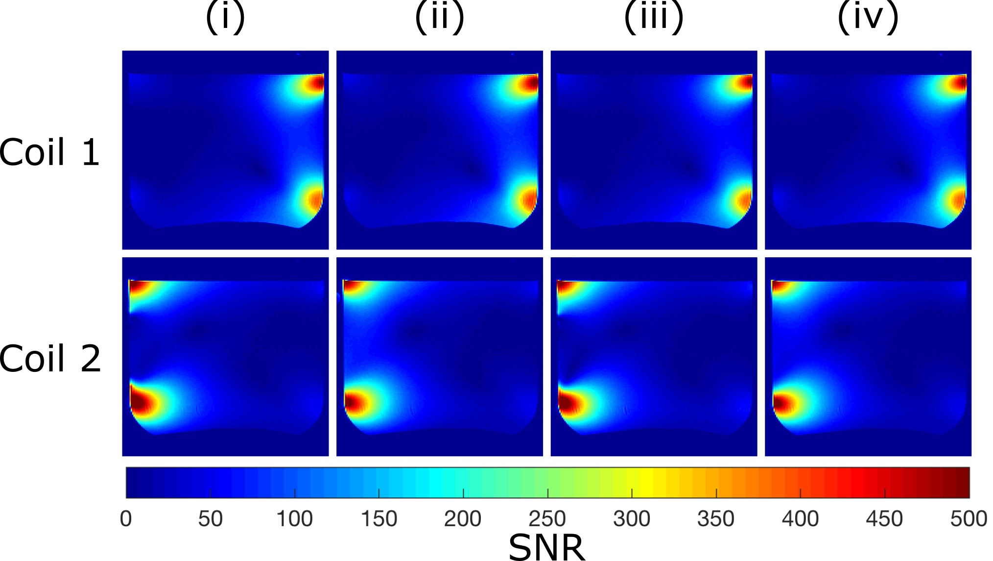
Figure 3: In column (i) no TMS coil present and a DL on
coil 2. In column (ii) no TMS coil present and no DL present on coil 2. In column
(iii) TMS coil and DL placed on coil 2. In column (iv) TMS coil on coil 2 and
no DL. Note: SNR values larger than 500 were truncated.
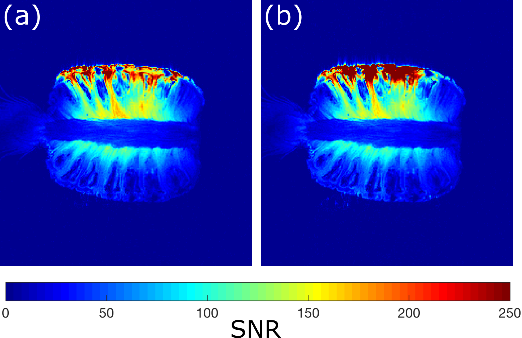
Figure 4: SNR calculated with anatomical images of (a) conventional
coil and of (b) coil using a dummy load. The TMS coil was not present in this
experiment. Note: SNR values larger than 250 were truncated.
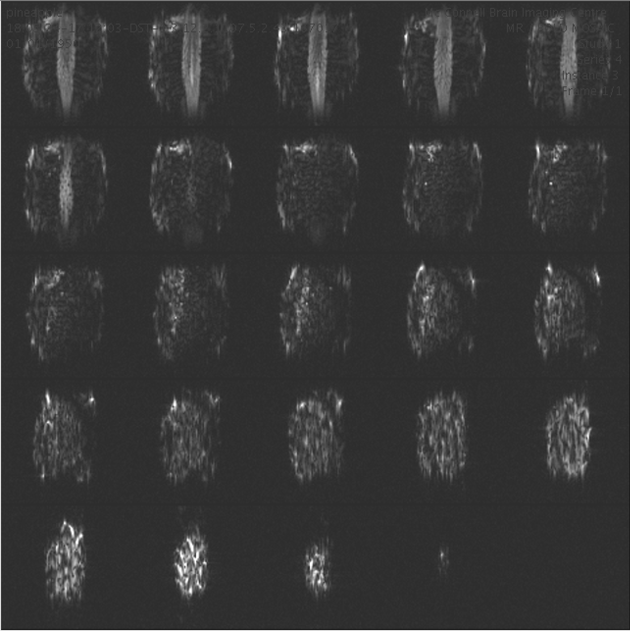
Figure 5: BOLD measurement of pineapple.