1515
Comparisons for microstrip and CRLH transmission lines array coils at 7T1Neuroscience Research Institute, Gachon University, Incheon, Korea, Republic of, 2Department of Biomedical Engineering, Gachon University, Incheon, Korea, Republic of
Synopsis
The use of Composite right/left handed (CRLH) metamaterial based transmission lines (TL) for high frequency applications can improve the magnetic field intensity and uniformity. This can be achieved independent from its physical length, contrary to the traditional microstrip TL. In this work we compare the |B1| and |E|-field of the CRLH TL with a common microstrip TL when used in an array of two elements. Three arrays with different lengths were compared, resulting in better field uniformity for the case of the CRLH TL.
Introduction
The development and advances of high magnetic fields MRI systems are promising in terms of better imaging capabilities; however these advantages also come with technological challenges, some of them brought by the use of high frequencies and the reduction of the wavelengths, reducing the uniformity of magnetic fields especially on the longitudinal (z)-direction. Transmission lines (TL) have been proposed to improve field uniformity [1], including the use of metamaterials as RF coils [2]. In this work we will compare the magnetic flux density (|B1|) and electric (|E|) fields, in terms of intensity and uniformity, of two types of TL array coils; a common microstrip TL (MTL) and a composite right/left handed (CRLH) metamaterial TL [3]. In general, the field produced by MTLs are dependent on their electric length, in the contrary CRLH TL exhibits field uniformity with less dependency on the physical length of the TL [4].Methods
We designed the MTL and the CRLH TLs according to the geometry for a quarter wavelength at 300 MHz with a length to 182.8 mm. In addition, to demonstrate the dependence on the physical length of each TL, a larger and smaller TLs of 200.7 and 160.1 mm length were also designed. Each TL had a width of 8 mm, a dielectric material of 2.54 mm thickness was used to separate with the ground plane. Each array consisted of two TLs separated by 10 mm that laid down over a dielectric and ground plane of 80mm width, as show in Fig. 1. The CRLH TL have gaps of 2mm length distributed evenly along the line, the gaps are used to include a series capacitor and inductor, in addition parallel capacitors and inductors connected to the ground plane are included as depicted in Fig. 1.Results
By means of electro-magnetic (EM) simulations (Sim4Life, ZMT) the |B1|- and |E|-field for each array configuration were acquired on a phantom of 50 × 80 × 255 mm size and separated from the TLs by 10 mm. The electrical properties of the phantom were 0.4133 S·m-1 for conductivity and 43.77 relative permittivity. The dielectric used for the TL had conductivity and permittivity 0.0001 S·m-1 and 2.2 respectively.
The TLs on this study were terminated with a short circuit (ZL=0). Each of the CRLH TL were tuned to 300 MHz with series and parallel capacitors and inductors values of [5.2pF, 2.8pF, 35nH, 17.5nH], [5.6pF, 3pF, 35nH, 17.5nH ], and [5.3pF, 2.8pF, 35nH, 17.5nH] for the 160 182 and 200 mm length TL.
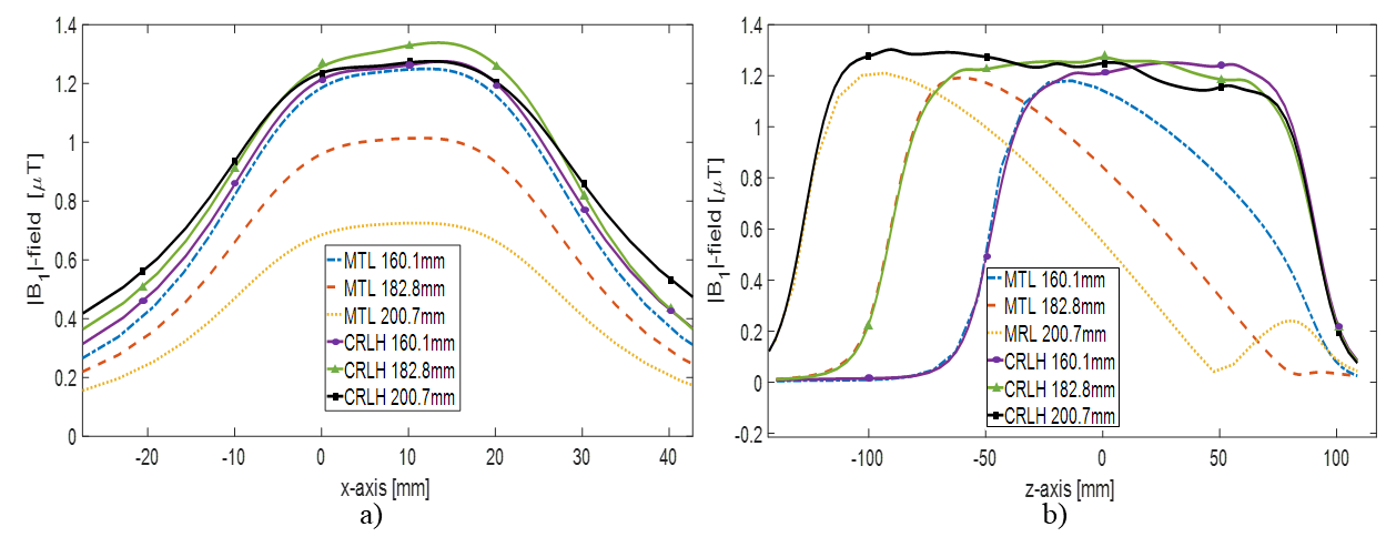
The |B1|-field for the quarter wavelength MTL and CRLH TLs are show in Fig. 2 for transversal (xy)- and (yz)-axis. To improve the field uniformity a 90 degree phase was applied between the TL. Figure 3 shows the line profile for each of the simulated arrays. The mean and standard deviation of the |B1|-field across the whole volume of the phantom for the MTL and CRLH arrays were [(0.17, 0.035), (0.18, 0.035), (0.17, 0.0334)] and [(0.34, 0.035), (0.37, 0.029), (0.38, 0.023)] mT for the 160, 182, 200 mm length TLs respectively.
The line profiles of the |E|-field on the (xy)-axis for each of the TLs with different length are shown in Fig. 4. The average value of the |E|-field for the MTL was 16.1 ± 4.4 V·m-1 while for the CRLH it was 21.4 ± 5.3 V·m-1.
Discussion
We compared the performance between MTL and CRLH TL arrays by acquiring the |B1|- and |E|- fields on a phantom. One of the notorious advantages of the CRLH is the ability to produce uniform fields along the (z)-axis despite the physical length of the TL, whereas in the case of the MTL the field tends to decay following the waveform.
When consider the CRLH as Tx coils the |B1|-field seem favorable over the MTL array both in terms of intensity and uniformity, however the |E|-field is also higher than the MTL array. The capabilities of the CRLH as Rx coil has the advantages of high field intensity which can translate to higher SNR compared to the MTL.
Conclusion
With the increase of field intensity of MRI systems the challenge of design RF coils that operate at higher frequencies will be necessary. The understanding of different technologies such as CRLH TL will be useful, especially when field uniformity for long imaging objects is required.Acknowledgements
This work was supported by a grant of the Korea Health Technology R&D Project through the Korea Health Industry Development Institute (KHIDI), funded by the Ministry for Health and Welfare, Korea (HI14C1135).References
1. Wang, C. and Shen, G.X., 2006. B1 field, SAR, and SNR comparisons for birdcage, TEM, and microstrip coils at 7T. Journal of Magnetic Resonance Imaging: An Official Journal of the International Society for Magnetic Resonance in Medicine, 24(2), pp.439-443.
2. Panda, V., Sohn, S.M., Vaughan, J.T. and Gopinath, A., 2016, June. A Zeroth Order resonant element for MRI transmisson line RF coil. In Antennas and Propagation (APSURSI), 2016 IEEE International Symposium on (pp. 1389-1390). IEEE.
3. Rennings, A., Mosig, J., Bahr, A., Caloz, C., Ladd, M.E. and Erni, D., 2009, March. A CRLH metamaterial based RF coil element for magnetic resonance Imaging at 7 Tesla. In Antennas and Propagation, 2009. EuCAP 2009. 3rd European Conference on (pp. 3231-3234). IEEE.
4. Lai, A., Itoh, T. and Caloz, C., 2004. Composite right/left-handed transmission line metamaterials. IEEE microwave magazine, 5(3), pp.34-50.
Figures