1513
A head transmit-receive array for a high performance gradient insert1Institute for Biomedical Engineering, ETH Zurich and University of Zurich, Zürich, Switzerland, 2Philips GmbH Innovative Technologies, Hamburg, Germany
Synopsis
Achievable gradient performance scales with decreasing gradient size which awakes interest in tight-fitting gradient coil design and requires space-restricted RF solutions. In this work, an eight-channel transmit-receive array coil for human head with a B1 field distribution preventing aliasing from the unambiguity volume of a high performance gradient insert and assuring a low eddy current capability is presented. In this configuration, acceptable homogeneous excitation and parallel imaging can be performed even despite the limited space for RF components.
INTRODUCTION
In a recently developed head-sized gradient system performance was maximized mainly by decreasing its size (1). In this way, applying slew rates up to 1200 mT/m/ms in vivo is not restricted by peripheral nerve stimulation.
Under this circumstances, the design of RF coils placed between gradient and subject face additional requirements and technical challenges. Obviously it has to be compact due to scarcely available space. Additionally, eddy currents running on RF coil structures need to be avoided as they scale up with increasing gradient switching rate. The sensitive volume of the RF coil should be restricted to the linear or at least to the unambiguous region of the gradient coil since the magnet’s uniform volume is larger than the working area of the small gradient insert.
We present an eight-channel transmit-receive array enabling parallel imaging of human head in a gradient insert with an inner diameter of 33cm (1).
METHODS
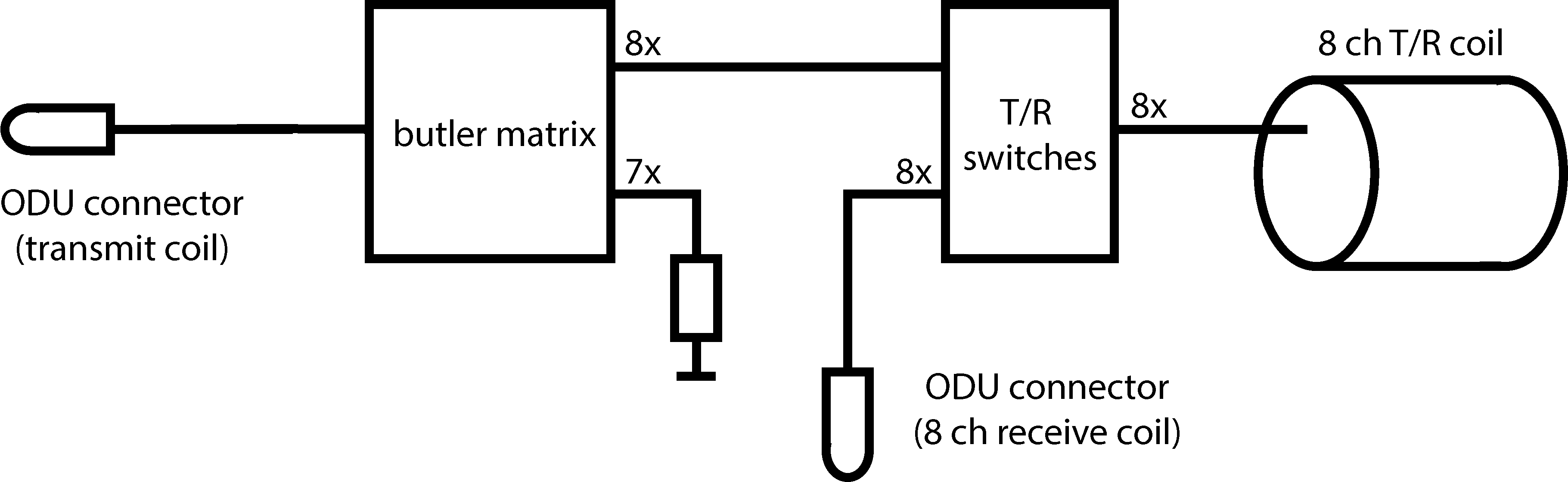
All measurements were performed on a clinical 3T human whole body system (Achieva 3T, Philips) in combination with the research gradient coil (1) replacing the RF body coil installed in the standard configuration. The RF coil was constructed by eight rectangular loop coils of 16 x 6 cm^2 circularly placed around a cylinder with a diameter of 24 cm. To reduce the radial extent of the array, the same elements are used for signal excitation as well as reception (2). Currents induced in neighboring elements are counteracted by suitably connected transformers (3) since usual preamplifier decoupling cannot be realized in transmit operation. To minimize eddy currents caused by gradient switching, the RF shield (diameter = 32.5 cm; length = 40 cm) is realized with a meshed conductive textile (holland shielding systems B.V.) (2) and coil conductors are bent cupper tubes with a diameter of 2 mm and a wall thickness of 0.4 mm. The interfacing of the coil to the scanner is illustrated in Figure 1.
Transmit performance was assessed by B1 maps (3) acquired in three volunteers (head circumference 55 cm to 59 cm). Power efficiency was calculated from the averaged flip angle in the brain. Noise correlation matrices were determined by noise using a human’s head as load. Parallel imaging capability is evaluated by g-factor maps (4) and demonstrated by artificially undersampled (1x2 and 1x3) 3D gradient echo images of human head with a Cartesian readout trajectory and an echo time of 0.42 ms (CUTE (5)). For a field of view of 24 cm x 24 cm this can only be reached by applying full slew rate (1200mT/m/ms) and gradients strength (100mT/m) in standard amplifier mode.
RESULTS
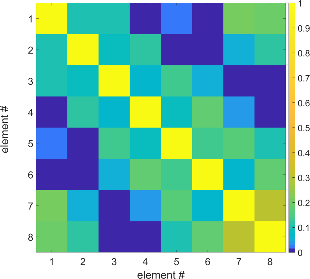
Coupling between neighboring elements as well as next-neighbors is below -12dB. This allows to tune and match each element to different loads almost independently of the others. Noise correlation is smaller than 0.31 (Figure 2).
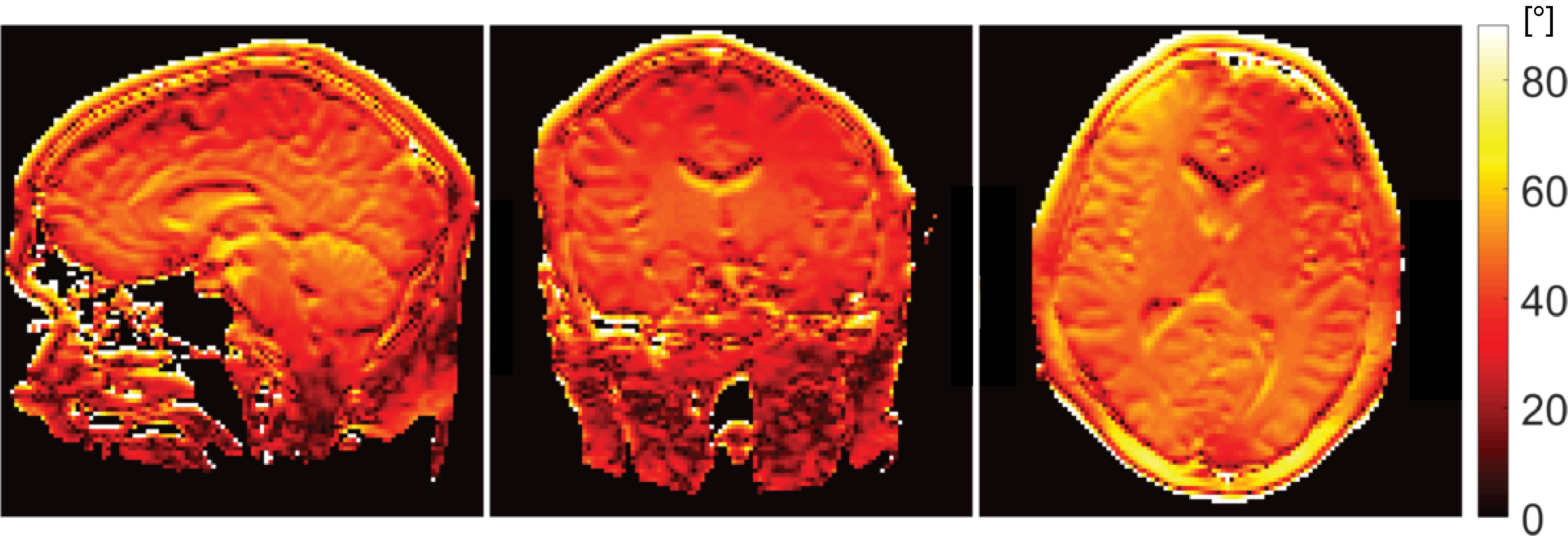
B1 field maps show flip angles in the requested range of 50° (Figure 3) and have similar appearance for the other subjects (data not shown). Transmit power efficiency is 0.52 ± 0.02µT/sqrt(W) for the three different human heads.
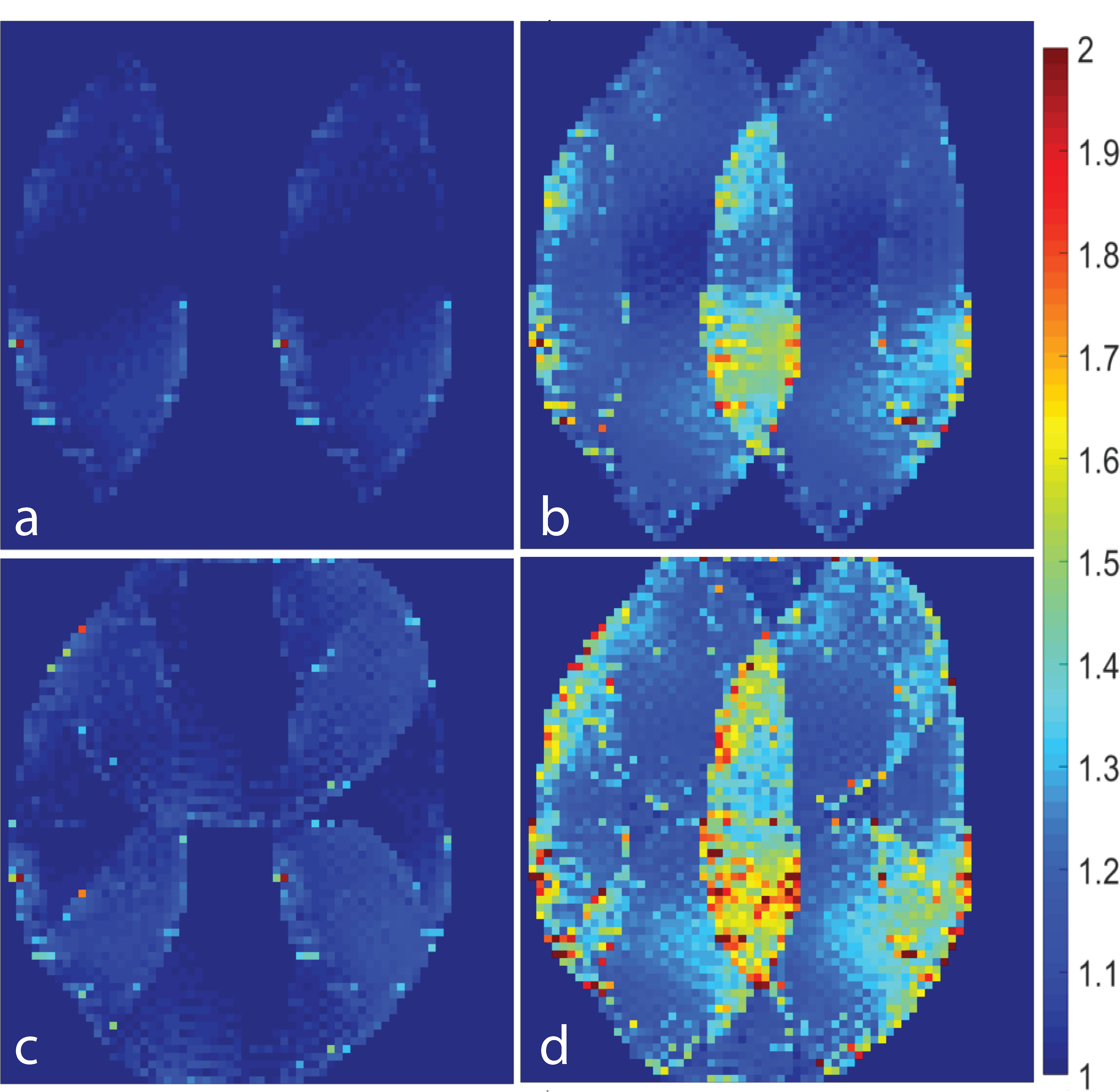
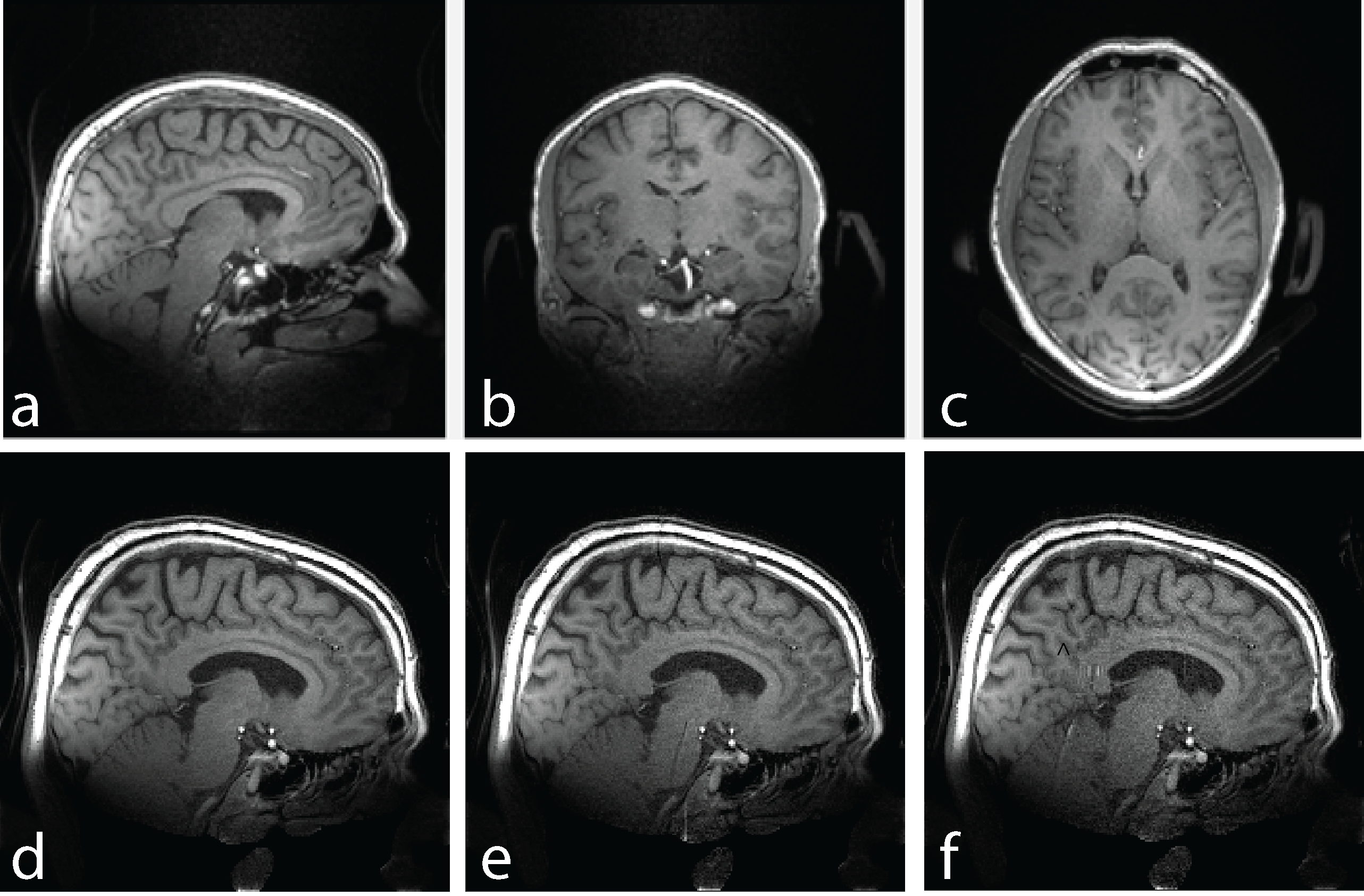
g-factor maps (Figure 4) show approximately 20% noise amplification for 1-x 2-fold and 2-x 2-fold accelerations in x and y direction respectively. For 3-fold accelerations in one direction noise amplification is increased up to 100%. Gradient echo images (Figure 5 a-c) show no aliasing of signal from tissue outside the ambiguity volume of the gradient and the desired T1-weighted image contrast in the brain. Figure 5 d-f show slight artifacts caused by artificially increased undersampling.
DISCUSSION
The power efficiency achieved with the array is sufficient for standard imaging applications, although it is naturally somewhat inferior to a shielded birdcage of similar size (0.6 µT/sqrt(W) (6)) mainly due to the additional coupling losses in the array. By operating arrays as transceivers, space-saving RF solutions can be implemented providing comparable parallel imaging performance as separated designs with the same channel count. In particular, with eight elements moderate noise amplification was obtained for 4-fold acceleration in two dimensions and depending on the application even 3-fold acceleration in one direction may be utilized. However, by using the same elements for signal excitation and reception the freedom to optimize field characteristics independently (field homogeneity vs. coil sensitivity/encoding capability) is lost.
The presented gradient echo images contain short-lived signal since the ear protection as well as the padding is visible. Oppose to images acquired at a longer echo time susceptibility artefacts e.g. close to the air sinus are reduced.
CONCLUSION
The presented array coil enables parallel imaging with a high performance gradient insert and therefore can be used to accelerate other acquisitions, e.g. echo-planar imaging, where it also contributes to a reduction of the Nyquist ghost.Acknowledgements
The authors are gratefully to Urs Sturzenegger from Philips Healthcare Switzerland for interfacing the RF coil with the scanner software.References
1. Weiger M, Overweg J, Rösler MB, Froidevaux R, Hennel F, Wilm BJ, Penn A, Sturzenegger U, Schuth W, Mathlener M, Borgo M, Börnert P, Leussler C, Luechinger R, Dietrich BE, Reber J, Brunner DO, Schmid T, Vionnet L, Pruessmann KP. A high-performance gradient insert for rapid and short-T2 imaging at full duty cycle. Magnetic Resonance in Medicine 2018;79(6):3256-3266.
2. Weiger M, Brunner DO, Schmid T, Froidevaux R, Rösler MB, Gross S, Pruessmann KP. A virtually 1H‐free birdcage coil for zero echo time MRI without background signal. Magnetic resonance in medicine 2017;78(1):399-407.
3. Yarnykh VL. Actual flip‐angle imaging in the pulsed steady state: a method for rapid three‐dimensional mapping of the transmitted radiofrequency field. Magnetic resonance in Medicine 2007;57(1):192-200.
4. Pruessmann KP, Weiger M, Scheidegger MB, Boesiger P. SENSE: Sensitivity encoding for fast MRI. Magnetic Resonance in Medicine 1999;42(5):952-962.
5. Hennel F, Weiger M, Rösler M, Luechinger R, Wilm B, Pruessmann KP. Cartesian UTE with Echo Time Below 0.5 Millisecond. ISMRM 25th Annual Meeting. Honolulu2017. p 1608
6. Rösler MB, Weiger M, Brunner DO, Schmid T, Froidevaux R, Pruessmann KP. An RF Birdcage Coil Designed for an Insert Gradient Coil Dedicated to Short-T2 MRI. ISMRM 25th Annual Meeting. Honolulu2017. p 2668
7. De Zanche N, Barmet C, Nordmeyer-Massner JA, Pruessmann KP. NMR probes for measuring magnetic fields and field dynamics in MR systems. Magnetic Resonance in Medicine 2008;60(1):176-186.
8. Dietrich BE, Brunner DO, Wilm BJ, Barmet C, Gross S, Kasper L, Haeberlin M, Schmid T, Vannesjo SJ, Pruessmann KP. A field camera for MR sequence monitoring and system analysis. Magnetic Resonance in Medicine 2016;75(4):1831-1840.
Figures