1512
A multi-function digital receiver for real-time data correction in MRI1Center for Basic MR Research, NorthShore University HealthSystem, Evanston, IL, United States, 2Department of Biomedical Engineering, Northwestern University, Evanston, IL, United States
Synopsis
We report the early development of an integrated receiver built on a Field Programmable Gate Array (FPGA). The receiver offers the functionalities of combining data acquisition, field sensing, real-time data correction and image reconstruction. We describe the design and implementation of the receiver and demonstrate its capabilities of image acquisition and reconstruction with real-time data correction.
Introduction
Imaging data acquired during MRI scans must be corrected if system hardware stabilities or the field at the volume of interest are perturbed. Real-time data correction is highly desirable because the expected data integrity should be preserved prior to image reconstruction. In this abstract, we describe the design for a multi-function digital receiver on a Field Programmable Gate Array (FPGA) and demonstrate its application to real-time data correction of system frequency shifts during MRI scans.Methods
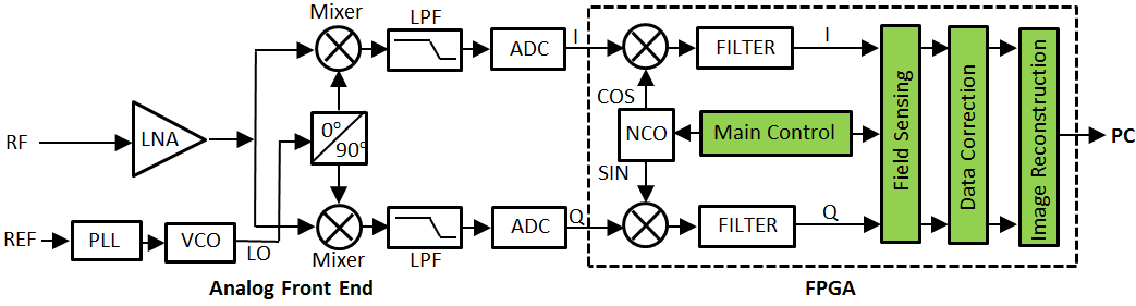
We designed and implemented the receiver based on a NI USRP-2940R board (National Instruments, Inc., Austin, TX, USA), as illustrated in Fig. 1. The receiver consists of analog and digital portions which are functionally divided by analog-to-digital converters (ADCs). Analog signal processing is performed with the analog front end; while digital signal processing is performed with the logic circuits built in an FPGA (a dashed box). After being conditioned and amplified by a low noise amplifier (LNA), an RF signal is down-converted to an intermediate-frequency (IF) signal using two mixers. The in-phase and quadrature components of the IF signal are then digitized with the ADCs to generate digital I/Q signals. Inside the FPGA, the digital signals are demodulated digitally with a signal from a numerically-controlled oscillator (NCO). For conventional digital receivers, at this stage, the demodulated I/Q signals are transferred either to specific DSP chips or to CPUs running on a host computer for image processing. In contrast, in our receiver, additional modules (green) are developed and implemented to perform field sensing, data correction and image reconstruction. Final images are generated after the baseband signals pass through these modules, Specifically, the Image Reconstruction module was largely based on a recently-developed 2D FFT module.1 The Field Sensing module was developed to determine quickly the frequency of the baseband signals. The Data Correction module was developed for real-time data correction prior to image reconstruction. The Main Control module was constructed with three major units: a timing-event sequence unit to control the receiver in response to an imaging sequence; a data management unit to coordinate all the modules inside the FPGA; and a unit to communicate with the host computer.
We used the architecture of PCI eXtensions for Instruments (PXI) and LabView (National Instruments, Inc., Austin, TX USA) software package as a development platform. All the modules were designed around an FPGA IC chip XC7K410T (Xilinx Inc., San Jose, CA USA). IF signals were sampled at 120 MS/s with 14-bit resolution; digital signals were processed at 80 MHz.
Results and Discussion
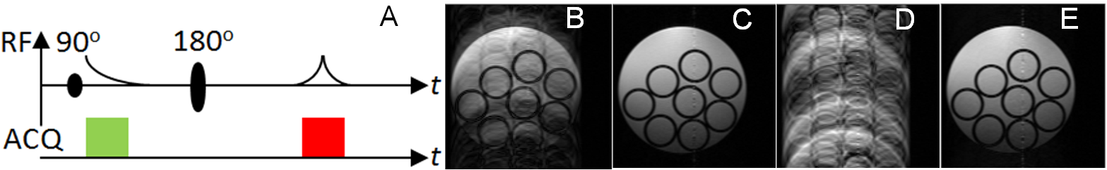
The receiver was tested with a series of spin-echo (SE) imaging experiments when incorporated with our Bruker BioSpec 94/30USR spectrometer. The receiver sent out a trigger signal to synchronize the data acquisition with the imaging sequence running on the spectrometer. The output port at the pre amplifier of the spectrometer was directly connected to the input connector of the FPGA board. A typical SE sequence (Fig. 2A) was applied to induce a FID signal for field sensing and an echo signal for imaging. To evaluate real-time data correction, at the beginning of every MRI scan, the frequency of the onboard direct digital synthesizer (DDS) was offset randomly from one phase-encoding step to next. The Field Sensing module detected the frequency shifts from the FID signals within 100 ns after the FID acquisition, which were used for immediate adjustments of the receiver NCO. Incoming imaging data were corrected by the Data Correction module in which phase coherence of the signals was performed. Fig 2B-E show the resulting images, with and without frequency compensation and data correction. These results verify that the receiver functions properly and can perform image reconstruction with real-time data correction. It is important to note that the frequency detection and compensation, data correction and image reconstruction were all performed on the same FPGA, unlike similar processes performed on a CPU.2,3 By integrating data acquisition and data processing on a single device, the receiver can eliminate unnecessary inter-device data routing, and thus enable real-time system adjustments or data correction of unpredictable and unreproducible system or field perturbations.Acknowledgements
This work was supported by NIH grant R21EB024852.References
1. Li L and Wyrwicz AM. Parallel 2D FFT implementation on FPGA suitable for real-time MR image processing, Rev. Sci. Instrum. 2018;89(9):093706. 2. Boer VO., et. al. Direct B0 field monitoring and real-time B0 field updating in human breast at 7 Tesla. Magn. Reson. Med. 2012;67:586-591. 3. Duerst Y, et al. Real-time feedback for spatiotemporal field stabilization in MR systems. Magn Reson Med. 2015;73:884-893.Figures