1511
B1 performance when excluding RF shields from transmit head coils to simplify multi nuclei and gradient insert setups1Radiology, University Medical Center Utrecht, Utrecht, Netherlands
Synopsis
RF shielding in MRI is used to enhance B1 efficiency of RF coils by reducing radiation losses and prevent coupling to surrounding materials like the gradient coil (1). However, RF shielding can also complicate the design of RF coils, particularly when used in multi-model setups, like for multi-nuclei experiments or when combined with gradient inserts. Here we demonstrate that the closely fitted RF shield of a head-coil can be removed to use the RF shield inside the bore liner of the MRI system in order to maintain high B1 efficiency.
Introduction
Efficient RF transmit head coils are generally designed with an RF shield, so to reduce radiation losses and to become less sensitive to the RF interaction of its surrounding. However, fast gradient switching can cause substantial eddy currents in these shields, complicating the design to maintain good gradient field performance. Moreover, in multi nuclei setups, often a 1H bodycoil transmitter is present (i.e. at 1.5T and 3T MRI) or even an integrated 31P RF bodycoil (7T, 2) which cannot be utilized if the shielded head coil is used. Here we compare the B1+ efficiency of non-shielded RF headcoil inserts with the same inner diameter tuned for hydrogen at 7T with state-of-the-art shielded headcoil: one integrated in an insert gradient (3) and 32 channel receive, and one in a 31P-1H setup using the bodycoil as transmitter (2) and 2 x 16 channel dual tuned receiver array.Methods
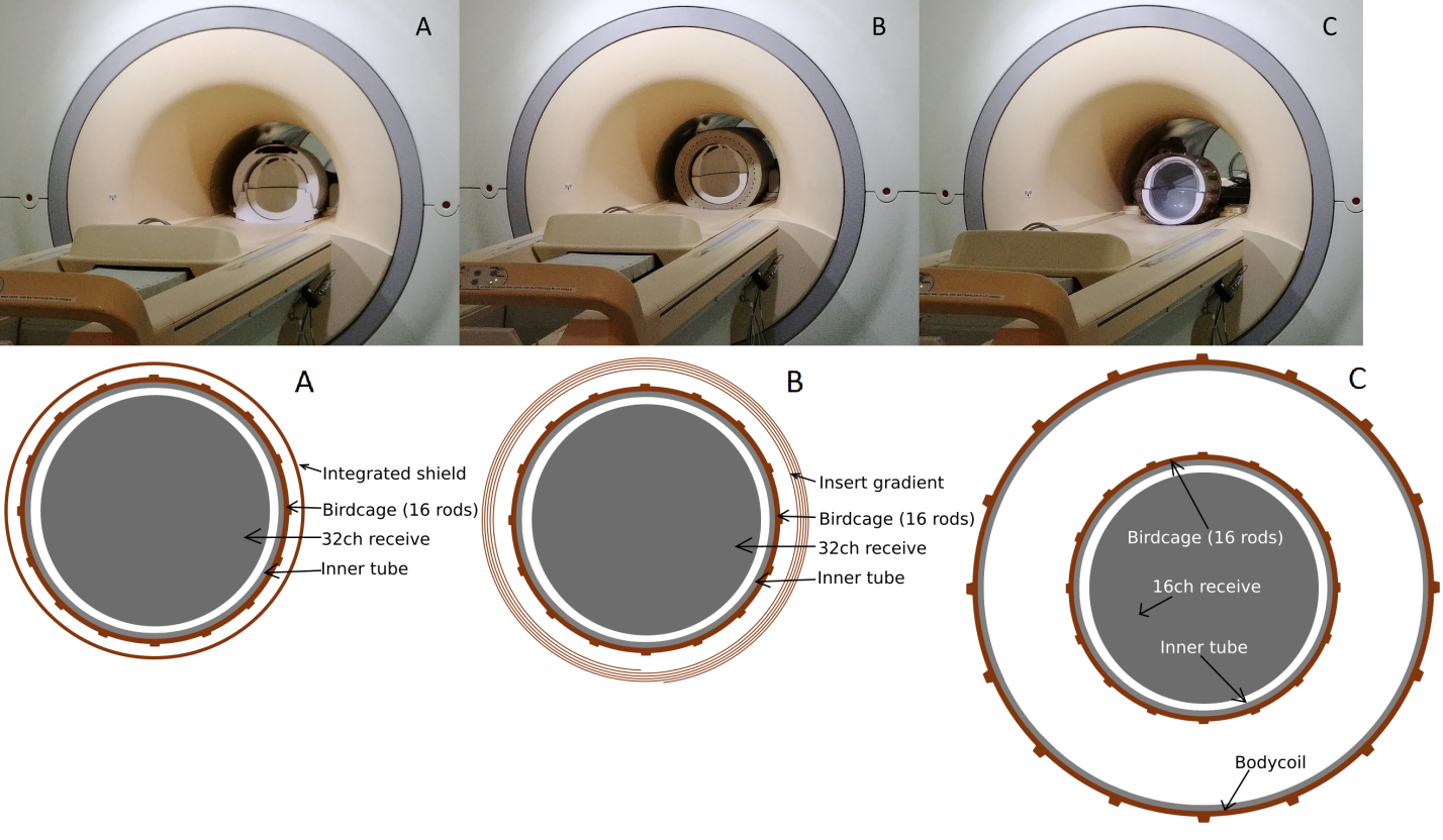
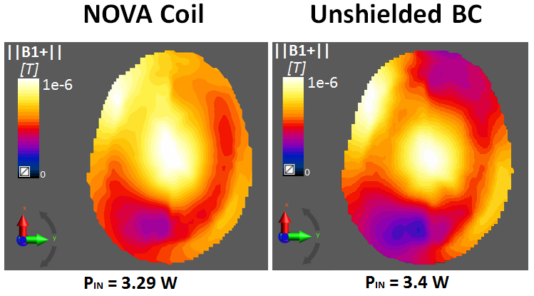
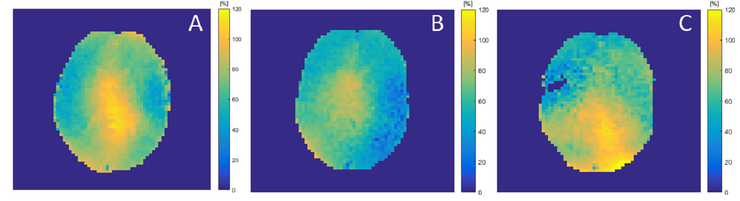
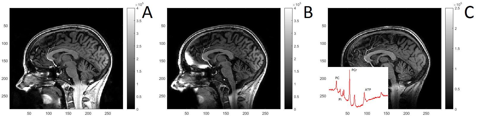
All experiments were compared to a dual transmit and 32 channel 7T headcoil (Nova Medical, Wilmington, USA, Fig 1a) interfaced to a 7T MRI system (Philips, Best, Netherlands). A non-shielded birdcage was designed and mechanically fixated inside a gradient-insert (Futura, Heerhugowaard, the Netherlands) wherein a 32 channel receiver array (Nova, USA) was positioned (Fig 1b). Another non-shielded birdcage was designed that was merged to an adapted 16 channel receiver array (Nova) that was made double tuned for 31P and 1H at 7T and used in conjunction with an integrated 31P bodycoil (2, Fig 1c). Both coils were made with the same dimensions and number of rods as the Nova headcoil: 32cm diameter, 21cm length, 16 rods. The coils were tuned inside a dummy shield that matches the dimensions of the RF shield behind the covers of the patient tube, and matched when loaded with a human head. B1 simulations were obtained with Sim4Life (Zurich Medtech, Zurich, Switzerland) using the conventional RF shielding and the bore shield on human model Duke (3). After obtaining local IRB approval B1 maps were acquired from all 3 setups using the same volunteer (DREAM sequence, FA = 7o, STE angle = 40o. FOV = 224 × 224 mm2, resolution = 3.5mm isotropic, TR/TE = 3.7/1.4) at identical RF power levels. This was followed by a 3D t1 weighted image (parameters FA = 7 o, FOV = 246 × 246 x 174 mm3, resolution = 1mm isotropic, TR/TE = 4.9/2.2).Results
The single tuned and single layer RF transmit coils could be easily integrated in the gradient insert and the dual tuned coil setup (Fig 1), yet the dummy bore shield was crucial for without the shield the uniform mode was invisible on the bench. Numerical simulations of the B1+ field per unit of power reflect a similar field distribution at a 3% reduction in efficiency (Fig 2). B1+ mapping at 7T demonstrate similar field distributions and a reduction in efficiency of 15.8% when integrated in the gradient insert and 2.6% when integrated in the multi nuclear setup (Fig 3). Good anatomical MRI can be obtained with all presented setups (Fig 4).Discussion and conclusion
At high fields (7T+), shielding of RF fields is beneficial for the performance of the RF coil. However, here we demonstrate that the RF shield of the bore coil can be used instead, thereby simplifying merging of technologies like incorporation of insert gradients and multi-nuclei setups. Still a small reduction of efficiency is observed, which could be compensated for by increasing the RF power.Acknowledgements
No acknowledgement found.References
1. Hayes CE., The development of the birdcage resonator: a historical perspective, NMR Biomed. 2009 Nov;22(9):908-18. doi: 10.1002/nbm.1431.
2. Löring J, van der Kemp WJ, Almujayyaz S, van
Oorschot JW, Luijten PR, Klomp DW., Whole-body radiofrequency coil for (31) P MRSI at 7 T, NMR
Biomed. 2016 Jun;29(6):709-20. doi: 10.1002/nbm.3517.
3. Van der Velden et al., (2017) , A lightweight gradient insert coil for high resolution brain imaging, ISMRM , #4329
4.
Christ A, Kainz W, Hahn EG, Honegger K, Zefferer M, Neufeld E, Rascher W, Jana
R, Bautz W, Chen J., The Virtual Family – development of surface-based
anatomical models of two adults and two children for dosimetric simulations, Phys.
In Med. & Biol., 209 Dec, DOI:10.1088/0031-9155/55/2/N01.
Figures