1510
Development of a 16 channel rotated double row transceiver array for neuroimaging at 7T1LUMC, Leiden, Netherlands
Synopsis
A 16 channel rotated double row transceiver array for imaging the human brain at 7T was designed using the recently developed induced current elimination decoupling method. The transmit and receive performance of the coil was characterized by in vivo measurements and compared to a commonly-used commercial two-channel transmit coil.
Introduction
MRI at high field strengths suffers from destructive B1 interference which reduces tissue contrast uniformity particularly in the temporal lobes1. It is well known that transceiver arrays combined with RF shimming can be used to improve B1 homogeneity2,3 and partially overcome these issues. A critical objective in the design of such a transceiver array is to minimize the coupling between the coil elements. Recently, an improved geometry for inductive current elimination (ICE) method was proposed4, facilitating a more homogeneous B1 field, especially close to the coil elements4. Here, we present a first performance test of a 16 channel loop array transce09oiver coil for 7 tesla using this ICE decoupling geometry.Methods
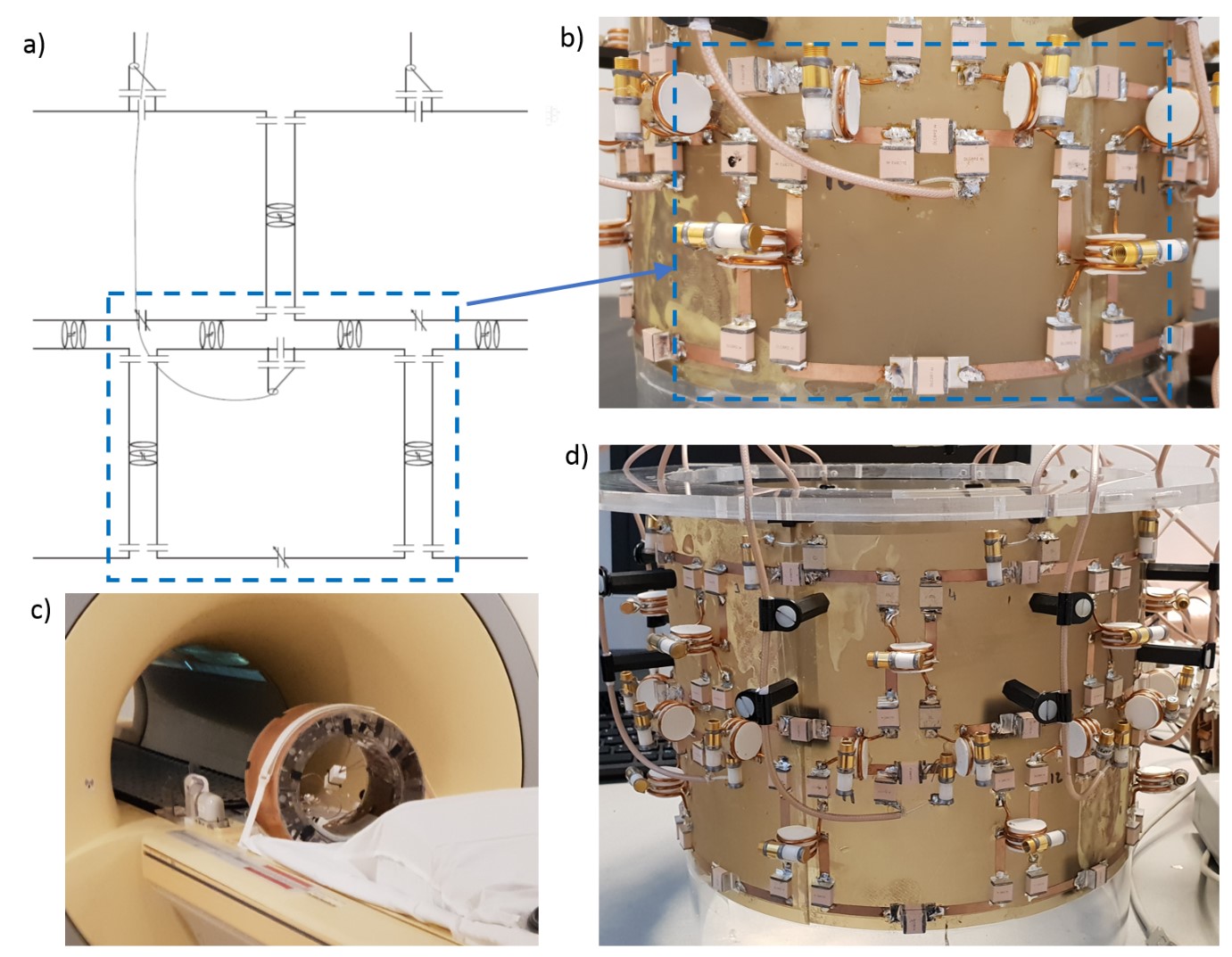
A 16 channel 7T transceiver coil was developed similar to the design of Shajan et al.3 at 9.4 T. Each channel consists of a loop (68x81 mm), positioned in two rows each containing eight loops and rotated 22.5o with respect to each other (Figure 1). Each element is decoupled from its four nearest neighbors by ICE, with the decoupling loops perpendicular to the coils to minimize the distortion of the B1+ field close to the coils4. To interface the 16 channels of the coil to the 8 transmit channels of the MR scanner, Wilkinson power dividers were used, connecting two neighboring elements per channel with one loop from each row.
Testing of this coil was done by scanning a headphantom5 (data not shown) and a healthy volunteer with a 7T Philips Achieva with both the 16 channel transceiver array and a commercial dual-channel birdcage transmit coil/32-channel receive array (Nova Medical) for comparison. The multi-transmit system of this scanner was used, which has 8 independent transmit channels. Both coils were driven in CP1+ mode excitation. For RF characterization B1+ maps and g-factor maps were measured as well as high resolution in vivo T1 images.
Results and Discussion
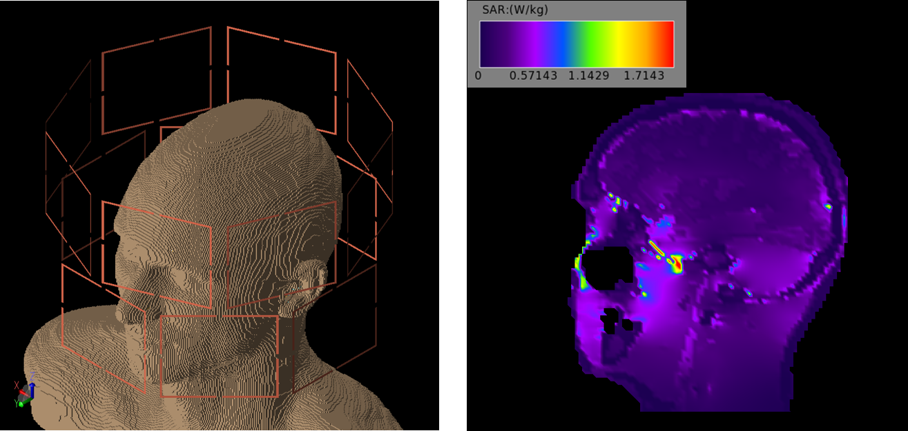
The S-parameters of the coil were determined using a network analyzer, showing that the nearest neighbor decoupling achieved with the ICE decoupling method was on average -22 dB. SAR simulations obtained through xFDTD (v7.4, Remcom inc., State College, PA) at an input power of 1 W showed a maximum 10-g average SAR of 0.71 W/kg and a head-average SAR of 0.20 W/kg. This meant that the maximum input power was 3W per channel, while satisfying the relevant SAR limits. The slice containing the maximum SAR10g is shown in figure 2, together with simulated phantom and coil elements.
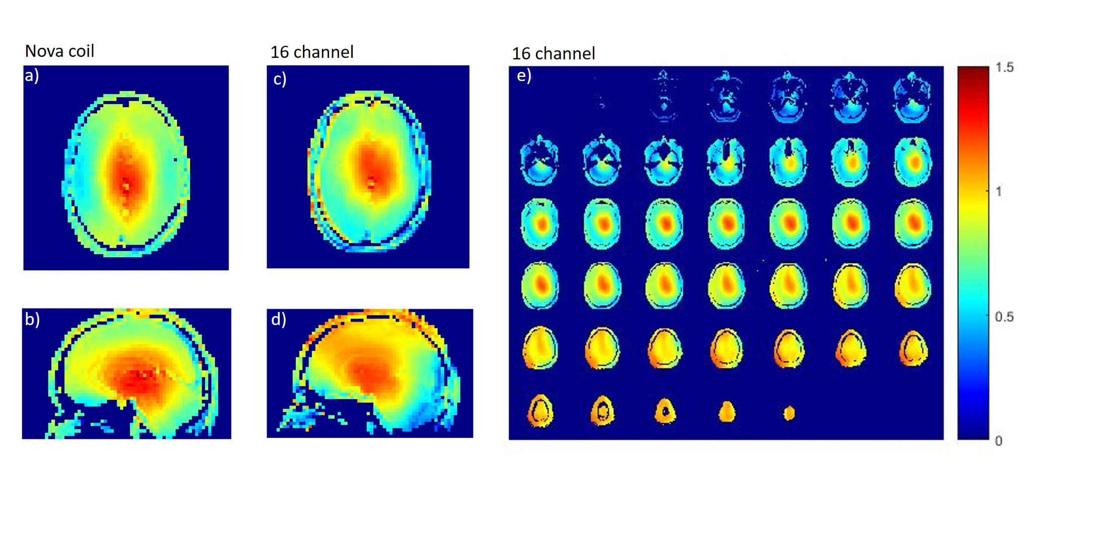
Figure 3(a-d) show B1+ maps in central axial an sagittal slices from both coils measured with the same settings. Input powers were calibrated as to achieve the same flip angle in both coils. Both coils show pronounced central brightening, with the 16-channel array having an improved B1+ towards the top part of the brain. The peak efficiency for the birdcage in the centre was 0.375 (uT/W1/2), while that of the array was 0.445 (uT/W1/2).
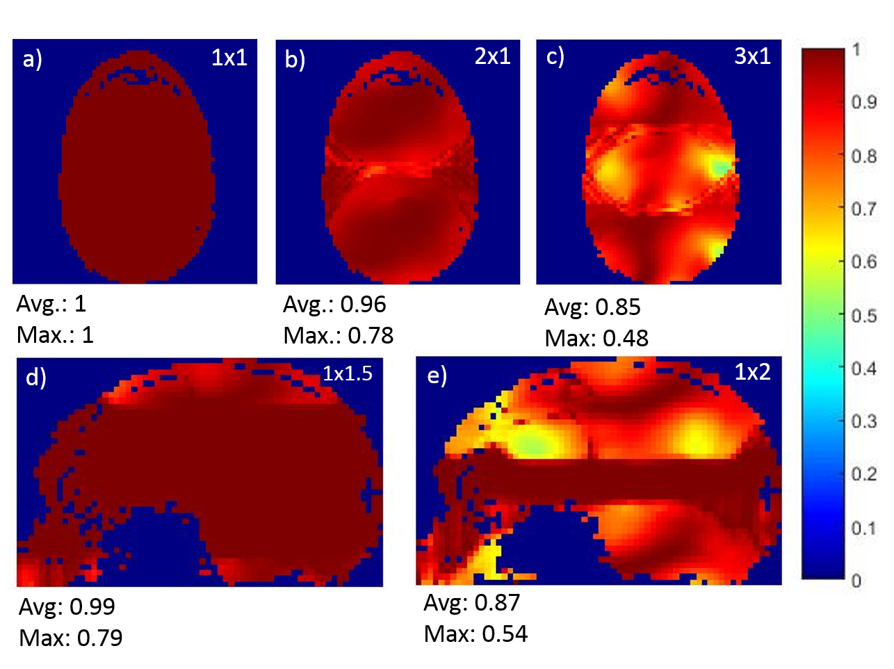
To determine the parallel imaging capabilities of the array, inverse g-factor maps were measured as function of both AP and FH acceleration, as shown in Figure 4b. For an acceleration factor of 2 in the AP direction and 1.5 in the FH direction low g-factors are observed indicating good parallel imaging behavior. For an acceleration of 3 in the AP and 2 in the FH direction we observe areas of higher g-factor values, indicating a reduced SNR in these areas when using SENSE with these acceleration factors. The higher g-factors in the FH direction is due to the coil geometry6, where the two rows are coupled by Wilkinson power dividers because of the limited amount of transceive channels of the MRI system.
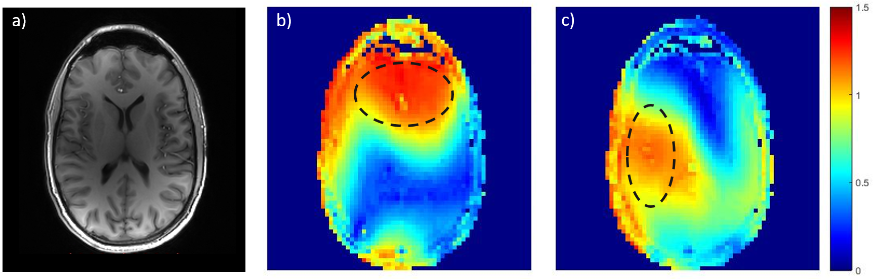
Figure 5a shows a transverse slice from a high resolution 3D T1w, indicating good contrast uniformity across the slice when the coil is used in the CP+ mode. In figure 5(b-c) B1+ maps are depicted showing the RF shimming capabilities of the transceiver array. Two areas were selected and RF shimming was used to maximize the B1+ field intensity and homogeneity in these areas. The B1+ maps clearly show improved B1+ homogeneity in the selected regions.
Conclusion
A 16 channel rotated double row transceiver array for imaging the human brain at 7T was developed and tested. In CP1+ mode B1+ maps measured with the coil showed increased B1+ in the top part of the brain when compared with a commercial dual-channel transmit coil. The parallel imaging capabilities were assessed by obtaining experimental g-factor maps, showing that SENSE can be used without significant signal loss using factors of 2 (AP) and 1.5 (HF). Finally it was shown that RF shimming can be used to target the B1 field to a specific region within the brain.Acknowledgements
No acknowledgement found.References
1 P.-F. Van de Moortele, C. Akgun, G. Adriany, S. Moeller, J. Ritter, C. M. Collins, M. B. Smith, J. T. Vaughan and K. Ug ̆urbil, (2005) B1 Destructive Interferences and Spatial Phase Patterns at 7 T with a Head Transceiver Array Coil. Magnetic Resonance in Medicine 54:1503–1518
2 N. I. Avdievich, (2011) Transceiver-Phased Arrays for Human Brain Studies at 7 T. Appl Magn Reson. 41(2-4): 483–506.
3 G. Shajan, M. Kozlov, J. Hoffmann, R. Turner, K. Scheffler and R. Pohmann (2014) A 16-Channel Dual-Row Transmit Array in Combination with a 31-Element Receive Array for Human Brain Imaging at 9.4 T . Magnetic Resonance in Medicine 71:870–879
4 Yan, X., Gore, J. C., & Grissom, W. A. (2017). New resonator geometries for ICE decoupling of loop arrays. Journal of Magnetic Resonance, 277, 59-67.
5 Wyger M. Brink, Zhiyi Wu, Andrew G. Webb (2018) A simple head-sized phantom for realistic static and radiofrequency characterization at high fields. Magnetic Resonance in Medicine 80:1738–1745.
6 K. M. Gilberta, A. T. Curtis, J. S. Gatia, L. M. Klassena and R. S. Menon, (2011) A radiofrequency coil to facilitate B1+ shimming and parallel imaging acceleration in three dimensions at 7 T. NMR Biomed. 24: 815–823
Figures