1508
On the SNR of Cryogenic Receive Coils when using Room Temperature Preamplifiers1Technical University of Denmark, Kgs. Lyngby, Denmark, 2General Electric, Brøndby, Denmark
Synopsis
Significant increase of the signal-to-noise ratio (SNR) is possible by cooling receive coils to cryogenic temperatures, if they are not highly sample noise dominated. Conventionally, the noise of the preamplifier is excluded leading to an overestimation of the achievable SNR gain. In this work, we show that for the case of a small-animal birdcage coil for 13C at 3T cooled with liquid nitrogen to 77K, the SNR is overestimated by approximately 40% if the effect of the room temperature preamplifier is excluded. Hence, the preamplifier should either be included in the SNR gain estimation or cooled with the coil.
Introduction
In low-$$$\gamma$$$ imaging, such as 13C, 23Na, and 14N, the sample loading is lower compared to 1H imaging. As a consequence, the electronic noise from coils and preamplifiers is dominating and has to be minimized to ensure efficient sample loading. Lowering electronic noise can be achieved by cooling copper coils with e.g. liquid nitrogen (LN)1 or using high temperature superconductors (HTS)2,3,4. Many of the articles dealing with cryogenic coils assume that the preamplifier is the same for both the room temperature and cryogenic coil.5 However, this may only be partially true because the noise figure of a preamplifier is defined in terms of the noise on the input, which depends on the temperature. Hence, even though the preamplifier is physically the same for the two cases, the noise figure changes in respect to the reference temperature. In this work, we present formulas for including the preamplifier noise based on noise figure simulations or measurements. Further, we show that, in many cases, excluding the noise added by the preamplifier yields too optimistic SNR gain estimates.Theory
The SNR gain when comparing a room temperature coil with a cryogenic coil is often described by
$$\Psi_{\textrm{coil}}=\sqrt{\frac{T^{\left(\textrm{r}\right)}\cdot{Q_{\textrm{u}}^{\left(\textrm{r}\right)}}^{-1}+T^{\left(\textrm{r}\right)}\cdot{Q_{\textrm{s}}^{\left(\textrm{r}\right)}}^{-1}}{T^{\left(\textrm{c}\right)}\cdot{Q_{\textrm{u}}^{\left(\textrm{c}\right)}}^{-1}+T^{\left(\textrm{r}\right)}\cdot{Q_{\textrm{s}}^{\left(\textrm{c}\right)}}^{-1}}},$$
where superscripted $$$\left(\textrm{r}\right)$$$ and $$$\left(\textrm{c}\right)$$$ refers to the room temperature and cryogenic coil, respectively. $$$T$$$ is the temperature of the coil, $$$Q_{\textrm{u}}$$$ is the unloaded Q-factor, and $$$Q_{\textrm{s}}^{-1}=Q_{\textrm{l}}^{-1}-Q_{\textrm{u}}^{-1}$$$ where $$$Q_{\textrm{l}}^{-1}$$$ is the loaded Q-factor. For the above equation, it is assumed that the preamplifier only adds a negligible amount of noise. However, if the preamplifier is used for both the room temperature and cryogenic coil, the noise figure (and thus the SNR impairment) increases as the reference temperature drops. This is because the noise figure is a relative measure. The usual reference is the equivalent noise generated by resistor at a temperature of $$$T_{\textrm{ref}}=290$$$K (as per the IEEE definition). Hence, when the reference temperature changes the noise figure also changes. The equivalent noise temperature is defined as
$$T_{\textrm{e}}^{\left(\textrm{r}\right)}=T_{\textrm{ref}}\left(F^{\left(\textrm{r}\right)}-1\right),$$
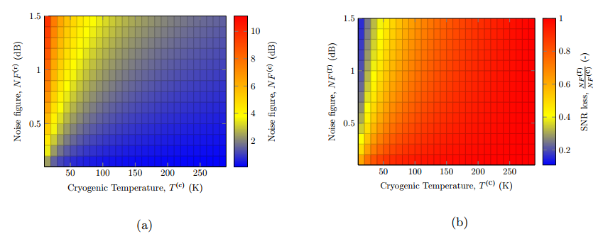
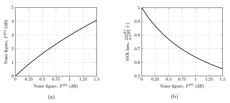
where $$$F^{\left(\textrm{r}\right)}$$$ is the noise figure of the preamplifier measured at a given reference temperature $$$T_{\textrm{ref}}$$$. Hence as the reference temperature is decreased by cooling the coil, while the equivalent noise temperature of the preamplifier remains constant, the resulting cryogenic noise figure increases as described by
$$F^{\left(\textrm{c}\right)}=\frac{T_{\textrm{e}}^{\left(\textrm{r}\right)}}{T^{\left(\textrm{c}\right)}}+1.$$
Extending the first equation with the following two yields
$$\Psi_{\textrm{coil+preamp}}=\Psi_{\textrm{coil}}\frac{F^{\left(\textrm{r}\right)}}{F^{\left(\textrm{c}\right)}}=\sqrt{\frac{T^{\left(\textrm{r}\right)}\cdot {Q_{\textrm{u}}^{\left(\textrm{r}\right)}}^{-1}+T^{\left(\textrm{r}\right)}\cdot{Q_{\textrm{s}}^{\left(\textrm{r}\right)}}^{-1}}{T^{\left(\textrm{c}\right)}\cdot{Q_{\textrm{u}}^{\left(\textrm{c}\right)}}^{-1}+T^{\left(\textrm{r}\right)}\cdot{Q_{\textrm{s}}^{\left(\textrm{c}\right)}}^{-1}}}\cdot\frac{F^{\left(\textrm{r}\right)}T^{\left(\textrm{c}\right)}}{T_{\textrm{ref}}\left(F^{\left(\textrm{r}\right)}-1\right)+T^{\left(\textrm{c}\right)}}.$$
Methods
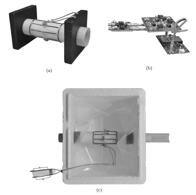
For SNR comparisons, a room temperature and cryogenic eight-rung low-pass quadrature transmit-receive (T/R) birdcage coil was constructed. The birdcage coils are mounted on a fiberglass tube with an inner diameter of 50mm and a thickness of 1.5mm. The coils have a length of 100mm and an inner diameter of 53mm. The conductor is 2mm diameter copper wire. A self-built RF front end consisting of a T/R switch, quadrature coupler, and preamplifier was used with a total noise figure of 1dB (at reference temperature of 290K) for the receive path. The cryostat is built using a styrofoam box where the cryogenic coil is completely submerged in LN. See Fig. 1. for pictures of the room temperature coil, cryogenic coil, and the RF front end.
The two coils were measured at 32.1MHz (13C) in a clinical 3T scanner (MR750, GE Healthcare, Waukesha, WI, USA) using a CSI sequence with TR=500ms and 30 degree flip angle. The sample was a 50ml tube with 30mm diameter and length of 120mm filled with ethylene glycol mixed with 1.7 NaCl g/L (to provide adequate loading).
Results
Simulated results are seen in Fig. 2 and 3. Bench measurements show $$$Q_{\textrm{u}}^{\left(\textrm{r}\right)}=362$$$, $$$Q_{\textrm{l}}^{\left(\textrm{r}\right)}=356$$$, $$$Q_{\textrm{u}}^{\left(\textrm{c}\right)}=627$$$, and $$$Q_{\textrm{l}}^{\left(\textrm{c}\right)}=616$$$. The corresponding SNR gain calculated using the first equation yields 2.5 whereas using the final equation yields 1.6.
Imaging experiments, seen in Fig. 4, yielded a room temperature SNR of 55.5 and a cryogenic SNR of 89.7. Hence, the measured SNR gain is 1.62.
Discussion
The conventional formula for comparing SNR between two coils at different temperatures overestimates the SNR gain, in this case, by approximately 43% (or 90% relative to unity) when comparing against the formula presented in this work, which includes the effect of the room temperature preamplifier. The small animal birdcage coils used for this comparison exhibit a poor sample loading of approximately 1.6% for the room temperature coil and 1.8% for the cryogenic coil. However, higher sample loading does not mitigate the relative SNR loss caused by the preamplifier.Conclusion
When designing cryogenic coils it is vital to include the SNR impairment caused by the preamplifier. Further, the preamplifier should be cooled together with the coil to achieve SNR gains upwards of 40% better as compared to using a room temperature preamplifier.Acknowledgements
This work was supported in part by the Danish National Research Foundation under grant DNRF124.References
1. J. D. Sanchez-heredia, E. Søvsø, S. Hansen, C. Laustsen, V. Zhurbenko, J. H. Ardenkjær-larsen, Low-Noise Active Decoupling Circuit and its Application to 13C Cryogenic RF Coils at 3 T, Tomography 3 (1) (2017) 60-66.
2. M. C. Cheng, B. P. Yan, K. H. Lee, Q. Y. Ma, E. S. Yang, A high temperature superconductor tape RF receiver coil for a low field magnetic resonance imaging system, Superconductor Science and Technology 18 (8) (2005) 1100.
3. J.-C. Ginefri, M. Poirier-Quinot, O. Girard, L. Darrasse, Technical aspects: Development, manufacture and installation of a cryo-cooled HTS coil system for high-resolution in-vivo imaging of the mouse at 1.5T, Methods 43 (1) (2007) 54-67.
4. I.-T. Lin, H.-C. Yang, J.-H. Chen, A Temperature-Stable Cryo-System for High-Temperature Superconducting MR In-Vivo Imaging, in: PloS one, 2013.
Figures