1506
A low SAR eight element passively fed meander dipole array for 7T prostate imaging1Radiology Department, C.J. Gorter Center for High Field MRI, Leiden, Netherlands, 2Imaging Division, University Medical Center Utrecht, Utrecht, Netherlands
Synopsis
The purpose is to compare the performance of an eight element passively fed meander dipole antenna designed for body MRI at 7 Tesla with that of a conventional actively fed array. The measured mean transmit efficiency (B1+/square root input power) in the prostate was 15% lower with the passively fed dipoles array, but the simulated max SAR10g was 44% lower, meaning that the overall SAR efficiency of the passively fed array is higher. In vivo RF shimmed turbo spin echo images showed similar image quality for both arrays, but with lower SAR values for the passively fed array.
Introduction
Dipoles have been shown both theoretically1 and experimentally2,3 to be efficient transmit elements for body imaging at 7 Tesla, and have also been used at higher fields. After the initial demonstration of a conventional dipole, much research has concentrated on optimizing the dipole geometry in order to maximize the transmit efficiency (B1+ field per square root of input power) and B1+ efficiency per maximum specific absorption rate (SAR), which act as appropriate figures-of-merit.
For all of the dipole geometries described so far in the MRI literature the element is fed directly via a partially- or fully-balanced lumped element network consisting of capacitors and/or inductors. However, it is also possible to feed dipole elements passively, i.e. via inductive and capacitive coupling of a passive dipole structure to a shorter dipole element which forms the feed point4. In this work, we evaluate experimentally and in simulations the passive feeding mechanism of a 300 mm long meander dipole antenna as part of an array element for prostate imaging at 7T.
Methods
The passively and directly fed meander dipole geometries are shown in Fig. 1. For a passively fed dipole, one side of the PCB (‘back’ side) contains a short feeding dipole (110 mm length). The other side of the PCB (‘front’ side) contains a larger radiating dipole and is oriented towards the phantom/subject. Eight directly and eight passively fed meander antennas with the same total dimensions were fabricated on an FR-4 substrate (ɛr =4.3, tanδ=0.025, substrate thickness 1.5 mm). The directly-fed meander dipole antenna has two identical matching capacitors with a value of 22 pF (Fig. 1). The passively fed meander dipole has a 33 nH inductor connected between the legs of a short feeding dipole and two identical 3.9 pF matching capacitors.
Electromagnetic simulations were performed in CST Microwave Studio 2016 (CST Studio Suite, Computer Simulation Technology, Darmstadt, Germany). The dielectric properties of the phantom used in the simulation were ɛr=50 and σ=0.6 S/m. Simulations of the eight element transmit arrays were performed on the voxel model Gustav. In body array simulations, B1+ and max SAR10g were normalized to 8W of accepted power.
In-vivo experiments were performed using a 7T scanner with eight channel parallel transmit architecture (Philips Achieva 7T). B1+ maps were obtained using DREAM sequence with the following parameters: field-of-view (FoV) = 400 x 320 x 25 mm, voxel size = 5 x 5 x 5 mm, slices = 5, FA = 10°, TE/TR = 1.97/15 ms, NSA=1, STEAM=50°. The sequence parameters used for in-vivo imaging are the following: T2-weighted TSE, TE/TR = 110/6000 ms, FA=90°, NSA=1, TSE factor = 20, FoV 250 x 380 x 16 mm, voxel size = 0.8 x 0.8 mm, slice thickness = 3 mm. Phase-based RF shimming was performed to obtain the maximum B1+ in the prostate of a healthy volunteer.
Results
Figure 2 shows simulated B1+ and SAR values. For the passively fed meander dipole antenna, the simulated B1+ field of a single element is essentially identical to that of the directly fed at depths greater than a few centimetres while the max SAR10g is reduced by 37%. In the simulated eight channel array, Figure 2, again there is almost no difference in B1+ field in the prostate region produced by directly and passively fed meander dipole arrays. Figure 3 also shows the in-vivo measured B1+ map using the DREAM sequence. The B1+ in the prostate region was around 15% lower for the passively fed dipole array, but the simulated max SAR10g was 44% lower for the passively fed dipole array, meaning that overall there is an increase in the SAR efficiency by 15% for the passively fed array. The SNR of the images in the prostate region was very similar for both configurations.
Discussion
The main attribute of passive feed networks in general are that they provide partial shielding of the conservative electric field in a driven device. In this particular case the conservative electric field is produced by scalar potential along the dipole conductor. Figures 2 and 3 show that the shielding of the conservative electric field significantly lowers SAR while the B1+ field distribution is not significantly affected.
Conclusion
This abstract has compared direct and passive feeding of single dipole elements as well as in array configuration for high field MRI applications. We have proposed a simple and general way of improving the performance, in terms of B1+per square root max SAR10g of dipole type transmit elements.
Acknowledgements
This work was funded by ERC NOMA-MRI 670629
References
Lattanzi R, Sodickson DK. Ideal current patterns yielding optimal SNR and SAR in magnetic resonance imaging: computational methods and physical insights. Magn Reson Med. 2012;68(1):286-304
Raaijmakers AJ, Ipek O, Klomp DWJ, Possanzini C, Harvey PR, Lagendijk JJW, van den Berg CAT. Design of a radiative surface coil array element at 7T:The single-side adapted dipole antenna. Magn Reson Med. 2011; 66:1488-1497.
Raaijmakers AJ, Italiaander M, Voogt IJ, Luijten PR, Hoogduin JM, Klomp DW, Van den Berg CA. The fractionated dipole antenna: A new antenna for body imaging at 7 tesla. Magn Reson Med. 2016;75:1366–1374.
Zivkovic I, O’Reilly T, Brink W, Webb A. Design of a passive feed network to increase the transmit efficiency of dipoles at 7T. 2018; Joint Annual Meeting ISMRM-ESMRMB 2018, Paris, France. Proc ISMRM #4434
Figures
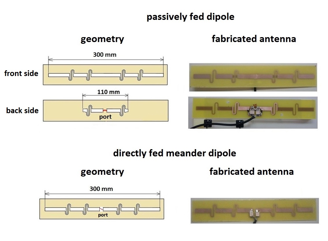
Figure 1. Photos and geometry of the fabricated directly and passively fed meander dipole antennas
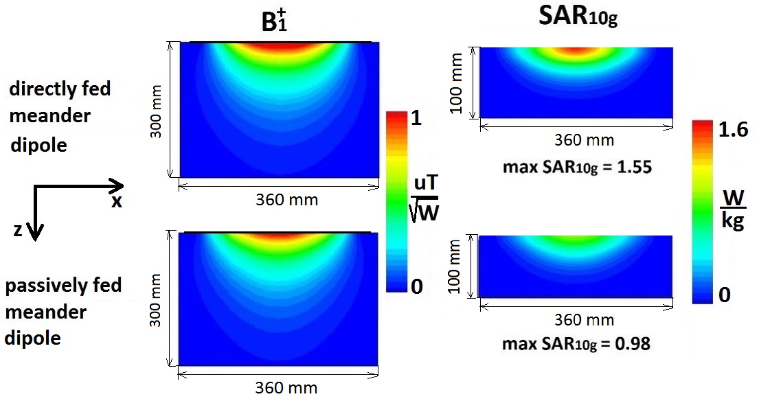
Figure 2. Simulated B1+ maps of directly and passively fed single meander dipoles on a phantom (left). Simulated max SAR10g of directly and passively fed single meander dipoles on a phantom (right, image dimensions are not scaled).
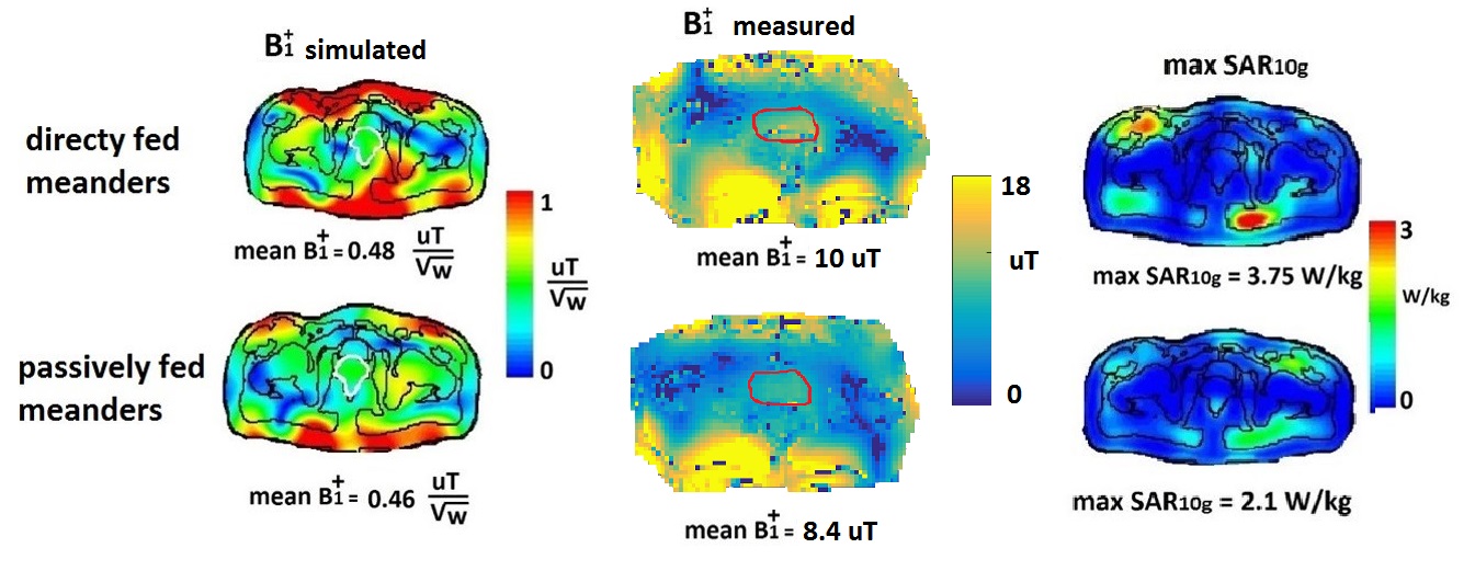
Figure 3. (left) Simulated phase shimmed B1+efficiencies (shimmed for maximum signal in the prostate and normalised to 8 W of accepted power) of the two eight channel arrays containing directly and passively fed meander dipole elements. (centre) In-vivo measured B1+maps. (right) Simulated max SAR10g (normalised to 8 W of accepted power) of the two eight channel arrays.
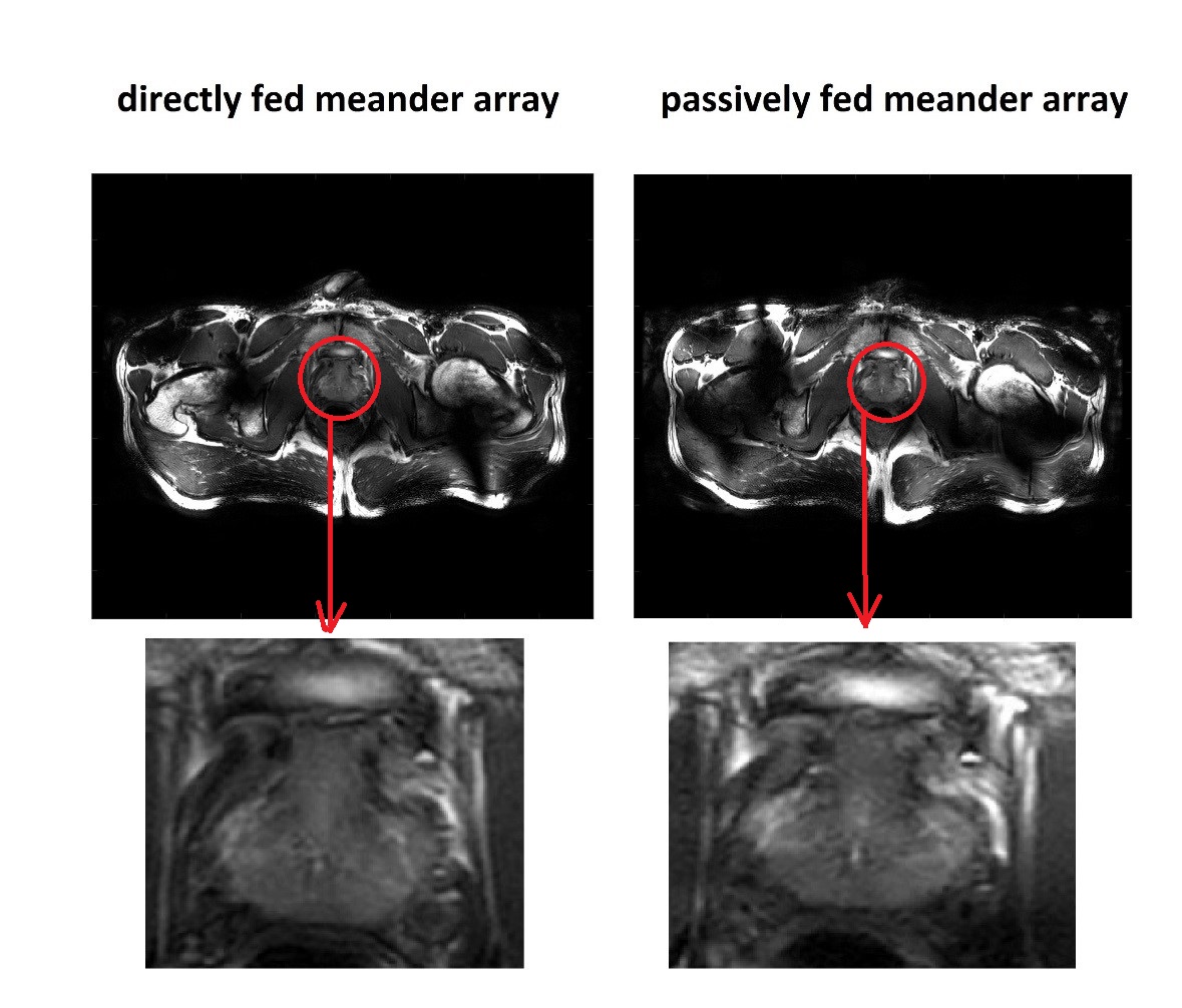
Figure 4. In-vivo TSE prostate images acquired from a healthy volunteer at 7T made with eight channel body array of directly fed meander dipoles (left) and array of passively fed meander dipoles (right). Phase-based RF shimming was performed to maximize the B1+ amplitude in the prostate. Zoomed-in images of the prostate are shown below.