1504
A radiolucent and flexible high impedance coil array to improve the imaging performance of a 1.5T MR-linac1Radiotherapy, UMC Utrecht, Utrecht, Netherlands
Synopsis
High impedance coils (HICs) are interesting for use in dense receive arrays for the MR-linac, as they lack lumped elements that attenuate radiation. Furthermore, HICs are flexible and exhibit low channel coupling, simplifying high-density array development.
We compared the performance of a 20-channel prototype setup with the current clinical array and investigated its dosimetric feasibility.
The prototype showed higher SNR values and lower g-factors, thus allowing for higher acceleration factors and faster imaging. Dosimetrically, no clinically significant attenuation was found (<1.5%).
In conclusion, flexible HIC based arrays are highly suitable to construct high density arrays for MRI-guided radiotherapy applications.
Introduction
The clinical receive array of the 1.5T MR-linac (Unity, Elekta AB, Sweden) contains only eight channels, which limits its parallel imaging (PI) capabilities. Additionally, the anterior element is elevated several centimeters above the patient to avoid anatomy deformations and minimize the skin dose.1 To increase the image quality and acquisition speed that are required for 3D time-resolved monitoring of the anatomy, we are developing a dense receive array for placement directly onto the patient. Contrary to diagnostic coils, coils in the MR-linac are irradiated through during the MRI-guided treatments and consequently no electronic components are allowed in the irradiation window, as they attenuate the photon beam. This radiolucency requirement complicates the coil design, as, e.g., no segmented placement of tuning capacitors is possible. Zhang et al.2 showed that high impedance coil (HIC) arrays do not require these tuning capacitors, can be flexible, and exhibit low channel coupling.
In this work we introduce HICs as a suitable approach for the design of a flexible dense on-body array for a 1.5 MR-linac to accelerate imaging by PI. We compare the imaging and acceleration performance of a 20-channel prototype setup with the clinical array and evaluate the dosimetric feasibility of this new design.
Methods
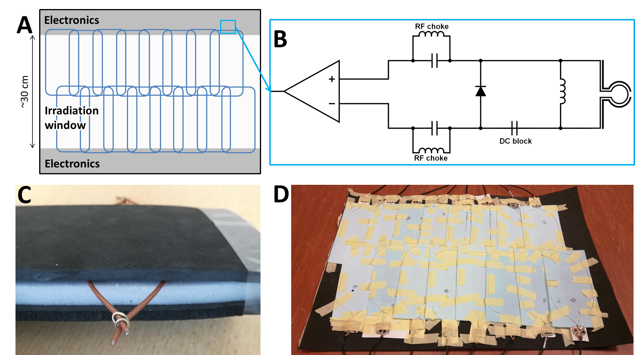
Design: The radiolucent design is shown in Figure 1. Only loops and support material are present in the irradiation window.
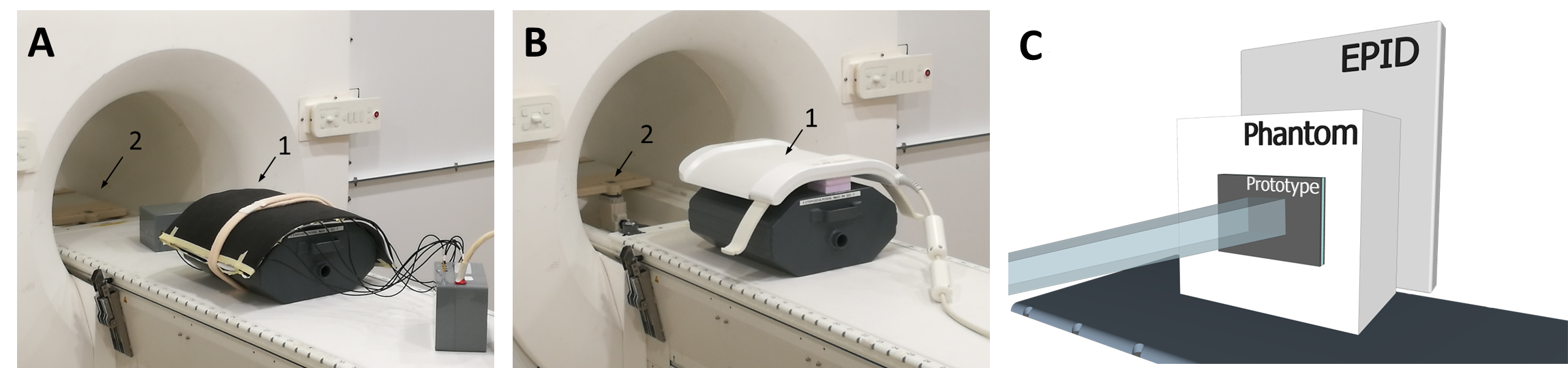
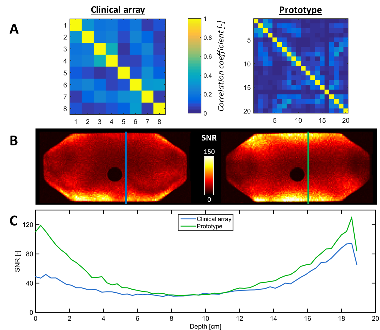
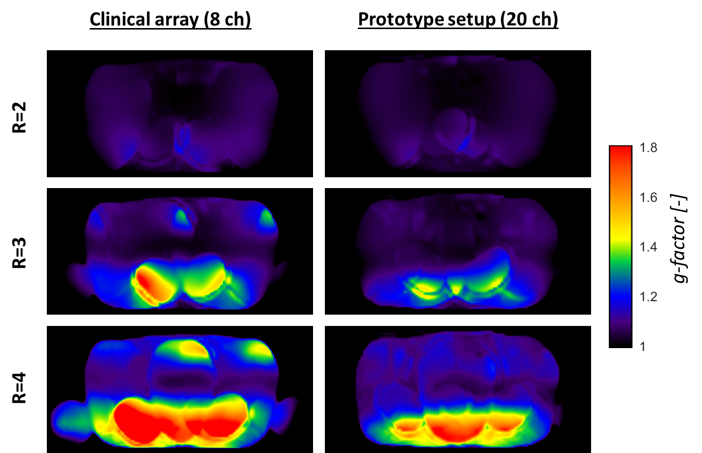
Imaging: Sixteen HIC loops (8.5×19 cm2) were constructed from AlphaWire 9432 (ø1.1 mm) coaxial cable to resonate at 63.87 MHz. A flexible array was manufactured with 5 mm foam above and 15 mm below the loops to reduce skin dose.3 Bending of loops during bench tests had negligible impact on their matching (<1 dB). A 20-channel prototype setup was created by combining the 16-channel anterior prototype and 4-channel clinical posterior element. This setup was compared with the clinical array that was placed in treatment position, i.e. elevated 4 cm above the pelvis-sized phantom (anterior element) and placed 3 cm under the table’s surface (posterior element). Imaging was performed on a 1.5T Elekta Unity (Figure 2a/b). First, inter-channel coupling was investigated by calculating the noise correlation coefficients. Subsequently, 50-dynamic 2D gradient echo acquisitions (TE/TR=4.0/30.0 ms, voxel size=3.0×3.0×10.0 mm3) were reconstructed using ReconFrame (Gyrotools, Switzerland) with sum-of-squares coil combination. The signal-to-noise ratio (SNR) was calculated with:$$SNR(x,y)=S_{mean}(x,y)/\sigma(x,y)$$where Smean(x,y) and σ(x,y) are the mean and standard deviation of the pixel intensity over time at location (x,y), respectively. Finally, the acquisition was repeated in-vivo with acceleration factors 2, 3, and 4 in left-right direction to generate g-factor maps.
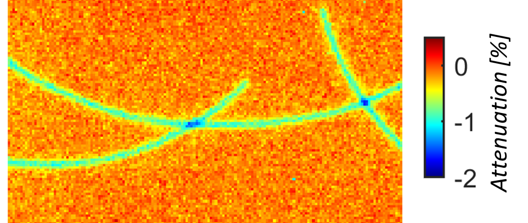
Dosimetry: A non-functional prototype was created with AlphaWire 9432 cable and low-density foam (Figure 2). 5×5 cm2 beams from 90° were delivered on an Elekta Synergy linear accelerator with and without prototype present (Figure 2c). On an electronic portal imaging device (EPID), 50-frame signal averages (pixel size: 0.35×0.35 mm2) were acquired and normalized4 and the attenuation Aprototype was then calculated with:$$A_{prototype}=(S_{prototype}-S_{open})/S_{open}$$
Results
Imaging: The prototype setup shows lower coupling coefficients than the clinical array (Figure 3a). In Figure 3b/c, a clear SNR increase is visible at the surface, after which the SNR becomes similar. G-factor maps of the prototype (Figure 4) show lower g-factors on the anterior side, especially at R=4.
Dosimetry: The attenuation map is shown in Figure 5. Dose changes
under a single cable and overlapping point are 0.83±0.12% and ~1.5%,
respectively. Surface dose increases (<0.08Dmax) were not clinically significant (results not shown).
Discussion
The presented design shows the imaging potential and dosimetric feasibility of HICs for a flexible 16-channel receive array for the MR-linac. HIC loops bend with negligible performance loss, which allows matching the shape of individual patients for optimal sensitivity without a loss of SNR. Furthermore, imaging shows an increase of the SNR at the surface and improved g-factor maps for our 20-channel prototype setup compared to the 8-channel clinical array, which enables the use of higher acceleration factors to speed up acquisitions. When the array is extended to 32 channels by constructing a posterior array, the additional channels are expected to further increase the SNR and, most importantly, improve the acceleration capabilities of the array. Dosimetry results show that the HIC prototype induces an attenuation of 0.8-1.5%. In the clinic such underdosages will not occur, as clinical multi-angle beam or volumetric arc treatments will smear out the slight underdosage. Consequently, the attenuation is not clinically significant. Body contour deformations are dealt with by the online replanning on the MR-linac5 and therefore pose no problems.Conclusion
HICs are suitable for use in receive arrays for the 1.5T MR-linac. The proposed array will lead to a higher local SNR and faster imaging, without clinically significant dosimetric consequences, for real-time anatomy monitoring during MR-linac treatments.Acknowledgements
This work is part of the research program HTSM with project number 15354, which is financed by the Netherlands Organization for Scientific Research.References
- Raaijmakers, A. J. E., Raaymakers, B. W. & Lagendijk, J. J. W. Integrating a MRI scanner with a 6 MV radiotherapy accelerator: dose increase at tissue-air interfaces in a lateral magnetic field due to returning electrons. Phys. Med. Biol. 50, 1363–1376 (2005).
- Zhang, B., Sodickson, D. K. & Cloos, M. A. A high-impedance detector-array glove for magnetic resonance imaging of the hand. Nat. Biomed. Eng. 1 (2018).
- Zijlema, S. E. et al. OC-0297: Dosimetric feasibility of on-body receive array placement to enhance image quality of the MR-linac. Radiother. Oncol. 127, S154–S155 (2018).
- McDermott, L. N., Louwe, R. J. W., Sonke, J. J., van Herk, M. B. & Mijnheer, B. J. Dose-response and ghosting effects of an amorphous silicon electronic portal imaging device. Med. Phys. 31, 285–295 (2004).
- Kontaxis, C. et al. A new methodology for inter- and intrafraction plan adaptation for the MR-linac. Phys. Med. Biol. 60, 7485–7497 (2015).
Figures