1502
Application of an RF Current Mirror for MRI Transmit Coils1Max Planck Institute for Human Cognitive and Brain Sciences, Leipzig, Germany
Synopsis
Some types of MRI transmit coils (e.g. Helmholtz coils) require equal currents in different coil elements. We present a novel feeding concept based on a passive RF current mirror, which ensures equal currents even if the loading and tuning of individual elements differ. Analytical equations are given for the dimensioning. It is demonstrated by simulations and experiments that the concept is viable, especially for ultra-high field imaging.
Introduction
It is well known that some radio-frequency (RF) coils require equal currents in different elements. This applies, for example, to Helmholtz coils, although at lower fields their loops can simply be connected in series. At higher field or for coils with more distant elements, these are usually fed separately via a power splitter. In this case, however, equal currents are not guaranteed if the loading and tuning of the elements differ. Therefore, a circuit that provides equal output currents would yield superior performance than a conventional power splitter. Subsequently, we refer to such an arrangement as an RF current mirror.Theory
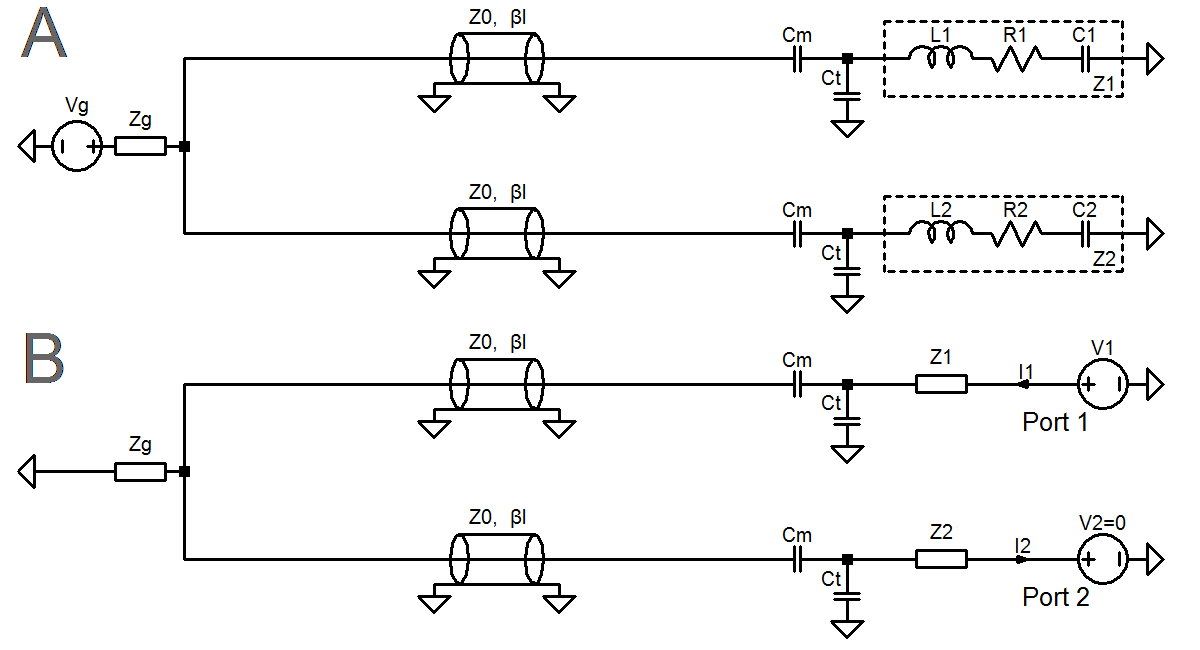
Since a certain spatial distance has to be bridged, it is apparent that the arrangement will include transmission lines. Therefore, for an initial analysis as illustrated in Figure 1A, we investigated if equal load currents can be achieved despite different loads $$$(Z_1≠Z_2)$$$. Upon setting $$$V_g=0$$$ and feeding a current $$$I_1$$$ into $$$Z_1$$$ (Figure 1B), the entire circuit becomes a network of cascaded 2-ports, and the ABCD-matrix$$$^\textbf{1}\:$$$representation is advantageous. The corresponding matrices for the components $$$Z_1$$$,$$$\:C_t$$$,$$$\:C_m$$$,$$$\:Tline_n$$$,$$$\:Z_g\:$$$and$$$\:Z_2$$$ are given by $$$\begin{pmatrix}1&Z_1\cr\:0&1\end{pmatrix}$$$,$$$\begin{pmatrix}1&0\cr\:i\,C_t\,\omega&1\end{pmatrix}$$$,$$$\begin{pmatrix}1&-\frac{i}{C_m\,ω}\cr0&1\end{pmatrix}$$$,$$$\begin{pmatrix}\mathrm{cos}\left(\beta\:l\right)\:&\:i\,Z_0\,\mathrm{sin}\left(\beta\:l\right)\:\cr\:\frac{i\,\mathrm{sin}\left(\beta\:l\right)\:}{Z_0}\:&\:\mathrm{cos}\left(\beta\:l\right)\:\end{pmatrix}$$$,$$$\begin{pmatrix}1&0\cr\frac{1}{Z_g}&1\end{pmatrix}$$$ and $$$\begin{pmatrix}1&Z_2\cr\:0&1\end{pmatrix}$$$, which have to be multiplied according to their order in the circuit. The element $$$D$$$ of an ABCD-matrix is defined as: $$D={\rm{ABCD}}_{2,2}=\left.\frac{I_1}{I_2}\middle|\mathop{}\limits_{V_2=0}\right.$$ Hence, considering the arrow direction (Figure 1B), both load currents are equal if: $$D=-1$$ Solving this equation for $$$\beta\:l$$$ yields, inter alia, solutions which contain neither $$$Z_1$$$,$$$\:Z_2\:$$$nor$$$\:Z_g$$$: $$\beta\:l\:=\:\frac{\pi}{2}-\mathrm{atan}\left(\frac{C_m\,C_t\,\omega\,Z_0}{C_t+C_m}\right)+k\pi,\:k=0,1,2,...$$ The result is the electrical length of both transmission lines (in radians) at which the original arrangement (Figure 1A) acts as the intended current mirror. No active components are required. We note that equivalent results for other kinds of matching networks can be obtained in a similar fashion.Experiments
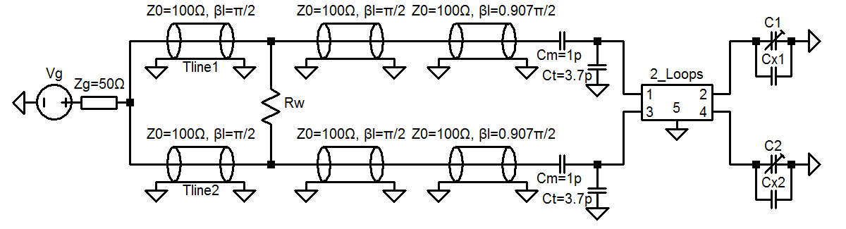
To
validate the theoretical finding, a setup was designed (Figure 2)
that could be easily simulated and realized experimentally.
A
simple Helmholtz coil (25mm loop radius and spacing; two opposite
gaps per loop) was selected for this purpose.
The
conductor was assumed
to be 4mm-wide
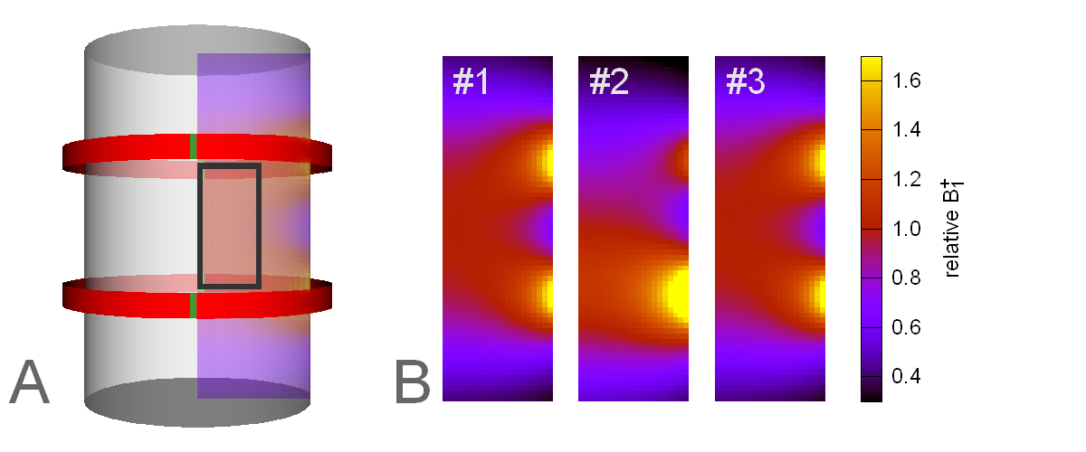
copper tape. An oil-filled cylinder (43mm
diameter, 66mm height)
served as phantom (Figure 3A).
A
particular goal was to easily switch between the conventional
operation mode ($$$R_w=200Ω$$$)
and the implemented current mirror
($$$R_w$$$
removed)
for a
direct
comparison.
In
contrast to the simplified
theoretical analysis,
the
transmission lines were modeled,
taking the skin effect and dielectric losses into account. The 3D
electromagnetic
field (EMF)
simulation and the RF circuit co-simulation were performed with
openEMS$$$^\textbf{2}\:$$$(v0.0.35)
and with LTspice (Linear Technology, Milpitas, CA, USA),
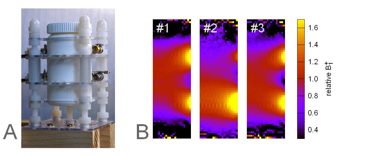
respectively. A
similar
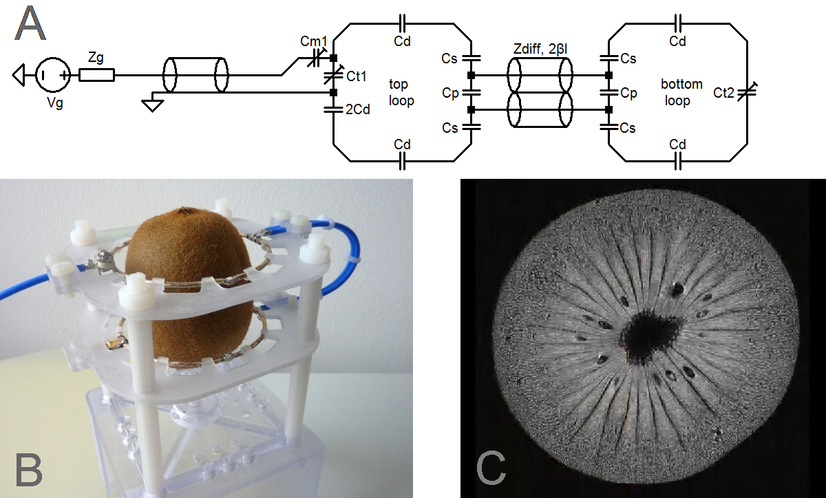
setup (Figure 4A) was built for use in a human-scale MRI
scanner
(MAGNETOM 7T, Siemens, Erlangen, Germany). In
this case,
balanced lines$$$^\textbf{3}\:$$$were
used, and the loops were made of 2mm silver-plated copper wire. Pure
polydimethylsiloxane$$$^\textbf{4}$$$
$$$(\textit{µ}=200~{\rm{mPa·s}},\:T_1=1.3~{\rm{s}})\:$$$
was used as phantom fluid.
The
coil
adjustment
was accomplished using a pick-up loop to achieve equal loop currents
initially.
Results and Discussion
The theoretical analysis predicts that the line length depends on the matching network but not on the coil loading. We note that this is similar to the concept of preamplifier decoupling in receive arrays, which requires identical cable lengths. This similarity can be employed for line-length adjustment. For further verification, simulations and experiments were compared for three conditions:
- Power splitter, loops tuned:$$$~~~~~~R_w=200Ω,~C_{x1}=1{\rm{pF}},~C_{x2}=1\rm{pF}$$$
- Power splitter, loops detuned:$$$~~R_w=200Ω,~C_{x1}=0,~~~~~~C_{x2}=2\rm{pF}$$$
- Current mirror, loops detuned:$$$~R_w=\:∞,~~~~~C_{x1}=0,~~~~~~C_{x2}=2\rm{pF}$$$
The corresponding $$$B_1^+$$$ maps are shown in Figures 3B and 4B from left to right. All maps were scaled by setting the mean value inside a region-of-interest (ROI) within the coil center (Figure 3A) to 100% with a color scale between 30% and 170%. As expected, detuning (condition #2) significantly deteriorated the homogeneity. After switching to current mirror mode (condition #3), homogeneity was restored. The experimental results are in good agreement with the simulations. Furthermore, the results show that the proposed concept also applies to coupled coil elements.
In the arrangement discussed above, the line lengths of the current mirror circuit are determined by the (fixed) matching network. This limits the practical applicability. A solution to overcome this limitation is to separate the feed from the current mirror (Figure 5), which achieves matching for a wide load range by adjusting $$$C_{m1},\:C_{t1}\:$$$and$$$\:C_{t2}$$$. In addition, there are new degrees of freedom for dimensioning, which require further investigation.
Conclusion
We have demonstrated a novel feeding concept, which is based on an arrangement that acts as an RF current mirror. It provides almost equal currents to individual coil elements (e.g. of a Helmholtz coil) which are independent of differences in loading or tuning of the individual elements.Acknowledgements
No acknowledgement found.References
$$$^\textbf{1}\:$$$ Pozar, D. M. (2005), Microwave engineering. Hoboken, NJ: J. Wiley.
$$$^\textbf{2}\:$$$Liebig, T., Rennings, A., Held, S. and Erni, D. (2013), openEMS – a free and open source equivalent-circuit (EC) FDTD simulation platform supporting cylindrical coordinates suitable for the analysis of traveling wave MRI applications. Int. J. Numer. Model., 26: 680–696. doi:10.1002/jnm.1875
$$$^\textbf{3}\:$$$Müller, R., Kozlov, M., Möller H.E. (2015), Balanced Feed Lines with Bridged Shield Gaps for RF Coil Arrays. Proc Intl Soc Magn Reson Med 23:1803
$$$^\textbf{4}\:$$$Skloss T. (2004), Phantom fluids for high field MR imaging. Proc Intl Soc Magn Reson Med 11:1635
Figures