1499
Prototype investigation for a size adaptable RF receiver coil capable of various body parts and sizes1Research & Development Group, Hitachi Ltd., Tokyo, Japan, 2Healthcare Business Unit, Hitachi Ltd., Tokyo, Japan
Synopsis
A size-adaptable RF receiver coil prototype which can displace inter-element distance with negligible SNR degradation was investigated. We applied a simple method to enhance blocking impedance of the preamp decoupling circuit by using intentionally small matching capacitance. SNR of the size-adaptable prototype was evaluated for phantoms of 5 sizes ranging from knee size to abdomen size against commercial coils dedicated for each body parts. Despite of its broad size adaptability across various body parts and sizes, the prototype showed higher SNR than each commercial coil.
Introduction
Generally, RF receiver coils are designed for dedicated body parts with fixed coil size. Even commercial flexible coils are usually restricted to fixed coil length which leads to insufficient adaptability to patient size. Not only a “one-size-fits-all” concept is desirable, but also a “one-coil-fits-all” concept capable of various body parts and patient sizes with a single type of coil would be even more cost effective. Several approaches have been considered to realize size-adaptable multi-channel RF coils.1-6 Challenges are to prevent SNR degradation due to inter-element coupling for a broad range of sizes with manageable manufacturing complication.
In this study, a size-adaptable RF receiver coil prototype which can displace inter-element distance with negligible SNR degradation was investigated. We applied a simple method to enhance blocking impedance of the preamp decoupling circuit7 by using intentionally small matching capacitance. Experimental SNR evaluation was conducted to check coil performance robustness when overlap of a neighbor coil was changed. For proof of concept evaluation, we made an 8-channel prototype to change overlap to fit various body parts or patient sizes and compared SNR of phantoms ranging from knee size to abdomen size against commercial coils dedicated for each body parts.
Methods
Decoupling method
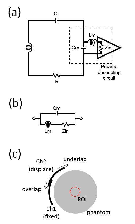
Fig. 1a is a schematic circuit diagram of a typical RF receiver coil with preamp decoupling. Fig. 1b is an equivalent circuit of the preamp decoupling circuit. The blocking impedance of the preamp decoupling circuit can be expressed with variables described in Fig. 1b as,$$\frac{1}{Z_{block}} = j\omega C_m + \frac{1}{j\omega L_m + Z_{in}}. (Eq. 1)$$ For typical MRI parameters where $$$\omega^2 C_m^2 Z_{in}^2 \ll 1$$$, Zblock can be simplified as, $$Z_{block} \sim \frac{1}{\omega^2 C_m^2 Z_{in}}. (Eq. 2)$$ With lower input impedance preamps, Zblock increases which enables preamp decoupling.7 Here, we propose to intentionally choose a small matching capacitance to enhance Zblock since it has a larger effect with a power of 2 compared to Zin.
Proof of concept evaluation
First, a bench measurement of Zblock with a
network analyzer was conducted for Cm = 12, 34, 59 pF and Zin = 0.6 and 1.2 Ω.
Second, SNR degradation due to neighbor
element displacement was evaluated with a 2-channel prototype with Cm = 12 pF.
Loop size were then chosen to be 90 mm by 180 mm placed at 7 mm distance from
the surface of a head sized cylinder phantom (diameter 165 mm, height 320 mm),
so that the coil was matched to 50 Ω at 3 T. The long end of the element was placed parallel to B0. Center
SNR (ROI 30 mm diameter) of the fixed channel was evaluated while the other was
displaced (Fig. 1c). For comparison, same measurement was made for Cm = 59 pF as conventional,
with 46 mm gap from the phantom for 50 Ω matching.
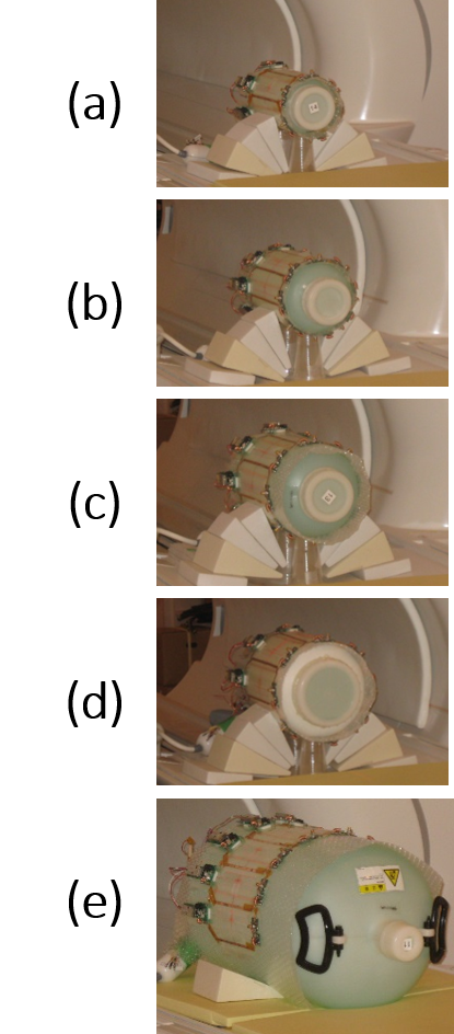
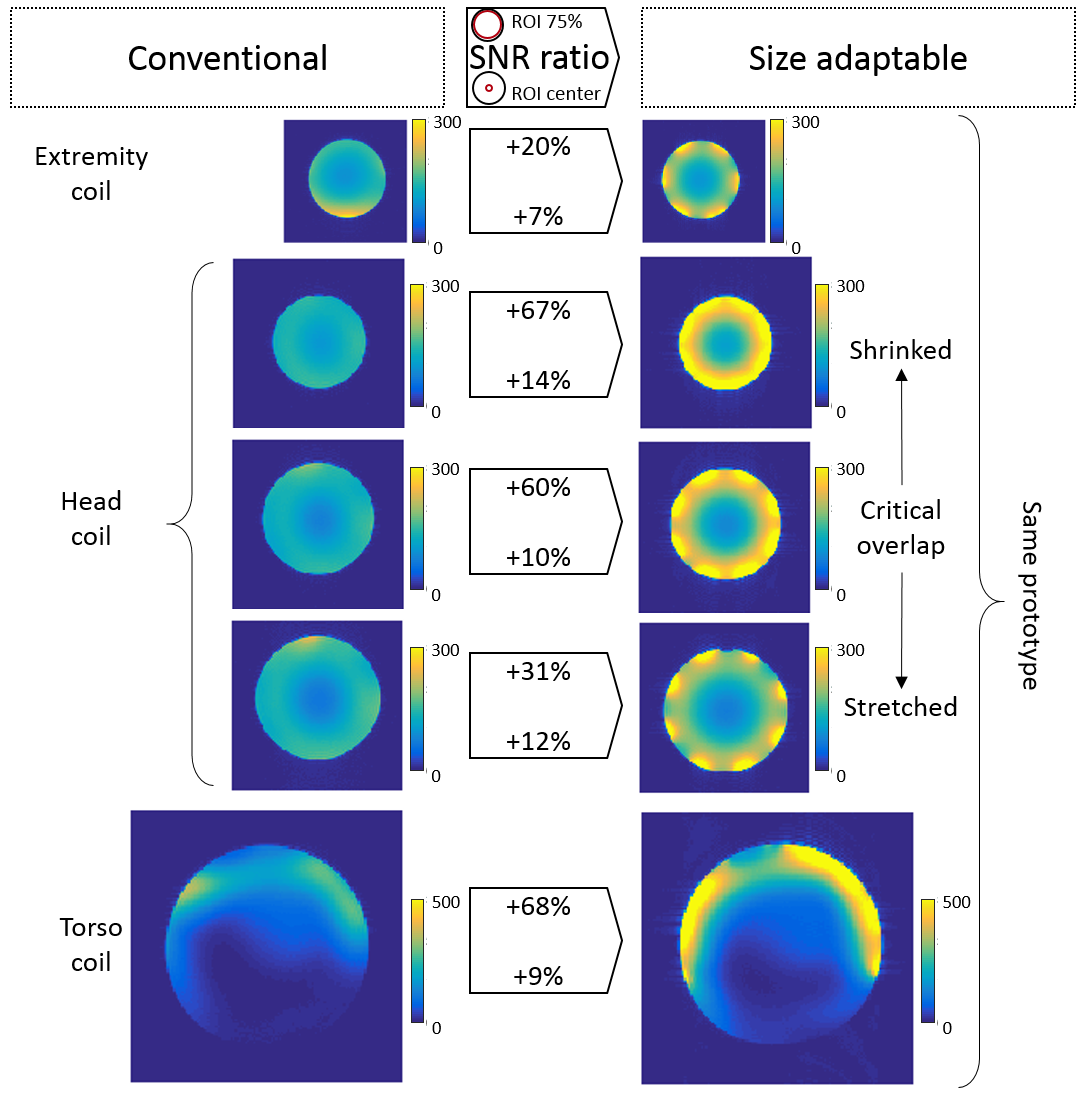
Third, an 8-channel prototype was made to
evaluate SNR for phantoms of 5 sizes (Fig. 2) with diameters of 121, 138, 165,
186 and 300 mm, respectively (phantoms A-E). The same elements of the prototype
were used for all phantom sizes without adjusting any circuitry. 8-elements
were used for phantoms B-E, and 6-elements were used for phantom A assuming
perfect detuning of the unused 2-elements. For comparison, commercial coils (Hitachi Ltd.,
Japan) closest to each phantom sizes were chosen; 12-channel extremity coil for
phantom A, 15-channel head coil for phantoms B, C and D, 12-channel torso coil
for phantom E. SNR was calculated with optimum reconstruction accounting noise
correlations.7 SNR of 75% area ROI and center ROI was compared. For all
scanning measurements, 2D SE sequence was used on a 3 T scanner.
Results
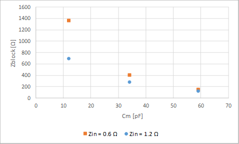
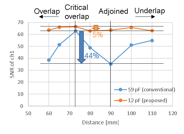
Fig. 3 shows bench measurement results of Zblock. A bigger enhancement of Zblock can be seen by smaller Cm than smaller Zin. Fig. 4 shows results of SNR degradation evaluation. SNR degradation was decreased to 5% from a conventional 44%. Fig. 5 shows SNR results of the size-adaptable prototype. Higher SNR was achieved for all 5 phantoms compared to commercial RF coils dedicated for each body parts.Discussion
Intentionally small matching capacitance lead to both close fit for higher SNR and decoupling enhancement. Further investigation is needed for magnetic field strength below 3 T, where sample loss is smaller compared to higher magnetic field strength.Conclusion
A size-adaptable prototype was investigated at 3 T, which can displace inter-element distance with negligible SNR degradation. Due to enhanced blocking impedance of the preamp decoupling circuit via intentionally small matching capacitance, the prototype showed high SNR performance despite of its broad size adaptability capable of various body parts and various patient sizes.Acknowledgements
No acknowledgement found.References
- J. A. Nordmeyer-Massner, et al., “Stretchable Coil Arrays: Application to Knee Imaging,” Magn. Reson. Med., Vol. 67, pp. 872-879, (2012).
- B. Wu, et al., “Flexible Transceiver Array for Ultrahigh Field Human MR Imaging,” Magn. Reson. Med., Vol. 68, pp. 1332-1338, (2012).
- G. C. Wiggins, et al., “Size-adaptable “Trellis” receive array concept for knee imaging,” Proc. ISMRM, pp.0493, (2016).
- P. Rossman, et al., “Characterization of a new ultra-flexible, low profile RF receive coil technology,” Proc. ISMRM, pp.0763, (2017).
- N. L. Rios, et al., “Size-adaptable 13-channel receive array for brain imaging in human neonates at 3 T,” Proc. ISMRM, pp.1053, (2017).
- B. Zhang, et al., “A high-impedance detector-array glove for magnetic resonance imaging of the hand,” Nature Biomedical Engineering, Vol. 2, pp. 570-577, (2018).
- P. B. Roemer, et al., “The NMR phased array,” Magn. Reson. Med., Vol. 16, pp. 192-225, (1990).
Figures