1498
Improved B1+ efficiency of a dipole antenna equipped with high dielectric constant (HDC) materials at 10.5TMyung Kyun Woo1, Lance DelaBarre1, Russell Lagore1, Steve Jungst1, Qing Yang2, Bei Zhang3, Sebastian Rupprecht2, Riccardo Lattanzi3, Mike Lanagan2, Maryam Sarkarat2, Kamil Ugurbil1, and Gregor Adriany1
1Center for Magnetic Resonance Research, Minneapolis, MN, United States, 2Pennsylvania State University, Hershey, PA, United States, 3Center for Biomedical Imaging, New York, NY, United States
Synopsis
We evaluated the performance of 10.5T RF coils composed of dipole antennas and high dielectric constant (HDC) ceramic materials placed in close proximity to the dipole antenna. We investigated the impact of the location of the HDC material relative to the dipole antenna. Both simulations and experimental verification indicate that a counterintuitive “Flipped” geometry positioning the dipole between the HDC material and the sample shows notable improvement in terms of the B1+ efficiency. We suggest further exploration of this new setup for ultra-high field (UHF) transmit arrays.
Introduction
High dielectric constant (HDC) materials have been adapted for MRI to improve SNR, transmit B1 efficiency, and B1 field uniformity [1-3]. Typically, HDC materials are positioned between the subject and the RF coil, and for many ultra-high field (UHF) applications with improved local B1 fields. Here, we explore the possible performance gains of a novel setup which flips the positions of antenna and HDC material. To investigate this, the B1+ efficiency of the “Normal” setup with object – dielectrics – antenna was compared with a “Flipped” setup of object – antenna – dielectrics. The comparison included arrangements where, both the flipped and the normal setups had the same distance between the dipole and the sample as well as a geometry where the dipole was placed close to the sample. Besides the two HDC dipole configurations we also evaluated for comparison an inductively shortened dipole of the same length [4]. All three configurations were compared in terms of B1+ efficiency relative to RF power used (B1+/√W) and relative to SAR (B1+/√W/√10g SARpeak) and verified experimentally at 10.5T.Methods
3D CAD renderings, photographs, and B-field patterns of the “Normal” and “Flipped” dipole antennas with HDC materials (TiO2) are shown in Fig.1. The HDC (σ= 0.0031 S/m and εr = 100) material was formed into two different shapes [5]. One is a flat disk (8.2 cm diameter and 1.6 cm thick) and the other is 15 cm long box shape (two-3.2 x 7.5 x 1.6 cm3 placed end to end) [6, 7]. An end-loaded dipole was built directly onto the HDC material with using one variable capacitor (Voltronics, NJ, USA). Experimental B1+ fields were obtained using an actual flip angle imaging (AFI) sequence for a cylindrical phantom (17 cm diameter and 30.5 cm long) with uniform electrical properties (σ= 0.6 S/m and εr = 49) at 10.5T [8]. B1+ fields were calculated in MATLAB (Mathworks, Inc., Natick, MA, USA) and were normalized to 1 W for B1+ efficiency (µT/√W). The B1+ efficiency (B1+/√W) and B1+/SAR (B1+/√W/√10g SARpeak) were compared for the (i)normal setup (Fig.2A), (ii)the flipped setup (where the dipole/HDC complex was at the same location relative to the sample as the normal set up but the dipole was placed on the proximal as opposed to the distal (relative to sample) surface of the HDC material) (Fig.2B), (iii)the flipped setup with the distance between dipole and the sample identical to the normal setup (Fig.2C) and (iv)a dipole without HDC materials that was shortened to be the same length as the HDC dipole by adding inductors at the feed-point. Simulated B1+ efficiency and 10g SAR were calculated using XFdtd (REMCOM, State College, PA) with 2 x 2 x 2 mm3 resolution. Fig.2 shows the B1+ efficiency calculated by the simulation and experiments comparison for the HDC disk. The dipole was either 3.2 or 4.8 cm away from the phantom. Fig.3 shows the same comparisons (minus the shortened dipole) for the rectangular HDC block both in simulation and experiment. The HDC block dipole was located either 4.8 or 6.4 cm above the phantom. The values of the HDC disk (Tab.1) and HDC block (Tab.2) are summarized and compared.Results and Discussion
Fig.1E shows the dipole and HDC material complex and the B1 field calculations around this complex. The related simulation and experimental results with the afore described configurations are shown in Fig.2 and Tab.1. The flipped setup shows substantially higher B1+ efficiency values compared to the normal setup or an inductively shortened dipole without HDC materials. When the distance between the dipole and the phantom is kept the same (Fig.2C) as the normal setup (Fig.2A), the flipped orientation still shows an improvement. The flipped setup also produced the highest performance of relative B1+/√W/√10g SARpeak. To ensure independence of this effect from the HDC material shape, a dipole with different dimensions built on a rectangular-shaped HDC block demonstrated the same trends, as shown in Fig.3. The material properties and physical dimensions of the HDC material influence the gains made by flipping the order of the dipole and HDC material. Simulations directed the choice of HDC block size demonstrated in Fig.3.Conclusion
For dipoles built onto HDC materials, the highest B1+ efficiency (B1+/√W) can be achieved when the antenna side faces the imaging sample and the HDC material facing away. These HDC dipoles show favorable B1+/√W/√10g SARpeak compared to the other setups studied and is thus expected to be the more efficient transmitter and by reciprocity receiver as well. We plan to expand this work by studying different geometries for array setup.Acknowledgements
NIH- U01 EB025144 S10 RR026783, BTRC P41 EB015894, P30 NS076408 and WM Keck FoundationReferences
[1] Neuberger T, Tyagi V, Semouchkina E, Lanagan M,Baker A, Haines K, et al. Concept Magn Reson Part B: Magn Reson 2008; Eng33B:109–114. [2] Qing X. Yang, Wei Luo, Sebastian Rupprecht, Zachary Herse, Christopher Sica, Jianli Wang, Zhipeng Cao, Jeffrey Vesek, Michael T. Lanagan, Giuseppe Carluccio, Yeun-Chul Ryu, and Christopher M. Collins. J Magn Reson. 2006; 24(1):197-202; 2 [3] Haines K, Neuberger T, Lanagan M, Semouchkina E,Webb AG. J Magn Reson 2009; 200:349–353. [4] Bei Zhang, Gang Chen, Martijn Cloos, Zidan Yu, Jerzy Walczyk, Christopher Collins, Ryan Brown, Riccardo Lattanzi, Daniel Sodickson and Graham Wiggins. In Proceedings of the 25th Annual Meeting of ISMRM, Honolulu, 2017. P. 4314 [5] Luo, W., Guo, J., Randall, C. and Lanagan, M., 2017. Effect of porosity and microstructure on the microwave dielectric properties of rutile. Materials Letters, 200, pp.101-104. [6] Russell L Lagore, Lance DelaBarre, Qing X Yang, Michael Lanagan, Yigitcan Eryaman, Sebastian Rupprecht, Wei Luo, Byeong-Yeul Lee, Xiao-Hong Zhu, Kamil Ugurbil, Wei Chen, Gregor Adriany. In Proceedings of the 25th Annual Meeting of ISMRM, Honolulu, 2017. P. 1128 [7] Myung Kyun Woo, Lance DelaBarre, Jerahmie Radder, Russell Lagore, Yigitcan Eryaman, Kamil Ugurbil, and Gregor Adriany. In proceedings of the 26th Annual Meeting of ISMRM, Paris, 2018. P. 24 [8] Beck BL, Jenkins KA, Rocca JR, Fitzsimmons JR. Tissue-equivalent phantoms for high frequencies. Concepts Magn. Reson. [Internet] 2004;20B:30–33. doi: 10.1002/cmr.b.20002.Figures

Figure 1. 3D CAD rendering, photographs and
B1 field pattern of an HDC disk with an end-loaded dipole attached
to it in the “Normal” setup (A, C, and E) and the “Flipped” setup (B, D, and
F). The blue dotted lines indicate the edge of the phantom.

Figure 2. B1+
efficiency - Simulation (µT/√W) , B1+ efficiency - Experiment (µT/√W), and B1+/√W
/√10g SARpeak (µT/√kg/W) maps with (A)
Normal setup, (B) Flipped setup, (C) Flipped setup maintaining the same
distance between the dipole and the subject as (A) and (D) Inductor-shortened
dipole without HDC materials that has the same dipole length as in (A-C). Blue and red dashed lines indicate the
location of dipole. Blue dashed lines of (A) and (C) indicate the same position
(4.8 cm) and red dashed lines of (B) and (D) indicate the same position (3.2
cm).
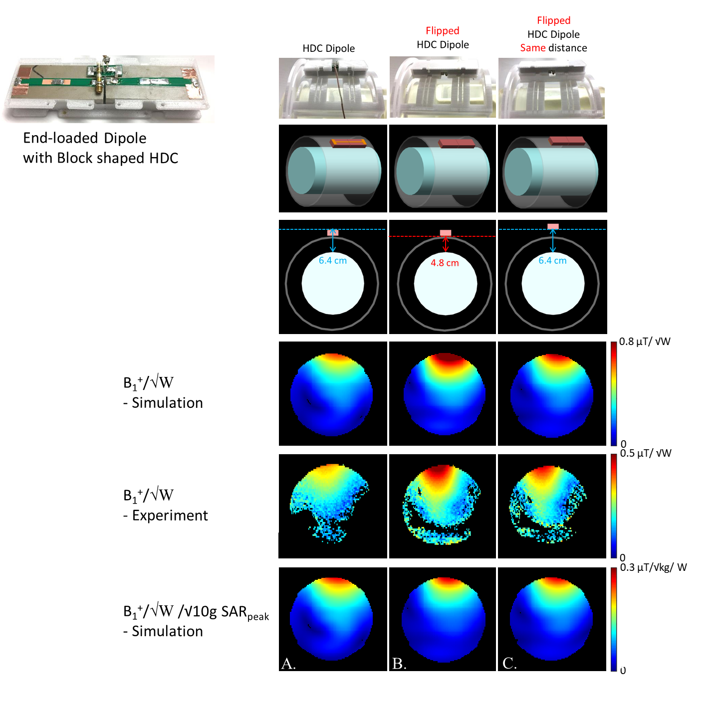
Figure 3. B1+
efficiency - Simulation (µT/√W) , B1+ efficiency - Experiment (µT/√W), and B1+/√W
/√10g SARpeak (µT/√kg/ W) maps with (A) Normal setup, (B) Flipped setup and
(C) Flipped setup at the same distance between the dipole and the subject as (A).
Blue and red dashed lines indicate the location of dipole. Blue dashed lines of
(A) and (C) indicate the same position (6.4 cm) and the red dashed line of (B)
indicate 4.8 cm away from the phantom.

Table 1. The highest point value of B1+
efficiency with the disk shape HDC - Simulation (µT/√W) , B1+
efficiency - Experiment (µT/√W), and B1+/√W/√10g
SARpeak (µT/√kg/ W) maps with (A) Normal setup, (B) Flipped setup, (C)
Flipped setup at the same distance between the dipole and the subject as (A)
and (D) Inductor shortened dipole with the same length of the dipole as (
A), (B) and (C) without HDC materials.

Table 2. The highest point value of B1+
efficiency with the two segmented block shaped pucks- Simulation (µT/√W) , B1+ efficiency - Experiment (µT/√W), and B1+/√W/√10g
SARpeak (µT/√kg/ W)
maps with (A) Normal setup, (B) Flipped setup, (C) Flipped setup at the same
distance between the dipole and the subject as (A) and (D) Inductor shortened
dipole with the same length of the dipole as (A), (B) and (C) without HDC
materials.