1497
A PET COMPATIBLE 17O/1H COIL FOR SIMULTANEOUS MULTINUCLEAR PET/MR1Department of Radiology, New York University Langone Health, Newyork, NY, United States
Synopsis
Direct MR oximetry by imaging 17O isotope can be a viable alternative over the conventionally used 15O PET tracer. In this work we developed a dual-tuned 17O/1H coil array with potential PET compatibility to explore brain oximetry and support simultaneous PET tracers to provide complementary insights into brain function.
Introduction
Brain homeostasis depends critically upon the steady nutritive flow of oxygenated blood, hinging on the immense energetic advantage of oxidative phosphorylation to sustain the neurovascular unit at rest and during explicit activation. Seminal paradigms describing hemodynamic compromise amid declining perfusion pressures were expounded through use of 15O PET, emphasizing a tenuous state of misery perfusion marked by impaired oxygen metabolism and conferring elevated near-term stroke risk1-3. Technical obstacles associated with 15O have motivated the exploration of direct MR oximetry, exploiting the stable and naturally occurring 17O isotope as an alternative to assess oxygen metabolism. However, its low natural abundance (0.037%) has demanded ultrahigh field imaging conditions coupled to fractionally enriched 17O gas inhalation, limiting widespread translational or clinical applicability4-7. In this work we developed a dual-tuned 17O/1H coil array with potential PET compatibility to explore the feasibility of natural abundance high sensitivity brain oximetry at 3T and supporting simultaneous PET tracers and molecular imaging providing complementary insights into brain metabolism.Methods
Design Approach: To achieve optimal multinuclear performance we engineered a co-planar interleaved coil8 comprised of two radially interleaved degenerate mode birdcage structures with four (17O, 16.7 MHz) and eight (1H, 123.2MHz) channels (Fig.1, 2). To minimize PET attenuation, we consolidated the arrays into a two "layer" structure, moved the interface components and majority of tuning capacitors outside the PET FOV, and enclosed the device in a 3D printed (Fortus 360, Stratasys) stealth polycarbonate shell.
17O Array: The 17O unit is a transmit/receive array with 4 elements (27 cm long (H-F) and 30 cm arc length). The neighboring elements were decoupled by geometrical overlap and the next nearest neighbors by linked inductors. The 17O array was driven in CP mode (using a 1:4 way power-divider and phase shifters) during transmission to achieve spin excitation; during signal reception the coil operated as a phased array to maximize SNR.
1H Array: The 1H unit is a receive only phased array with 8 elements (24 cm long and 12 cm arc length). The neighboring elements were decoupled by capacitors in the shared rungs. One active detuning circuit and one current fuse (700 mA) were implemented per 1H element to ensure patient safety and to isolate the array during body coil transmission, which was favored due to its large excitation coverage for applications such as spin labeling.
Trap Circuits: The perimeter of the oxygen loops is 114 cm, long enough to support standing waves at 123.2MHz. To ensure patient safety during body coil excitation, two 1H trap circuits were incorporated per 17O element.
Imaging: Phantom and in vivo measurements were performed using a whole-body 3T scanner (Prisma, Siemens Healthineers, Germany) upon approval by our local IRB and informed written consent from the participants. 17O images were acquired using a FLORET9 sequence. The 1H performance was compared against a standard clinical head array (Head/Neck 20, Siemens). 1H B1+ and SNR maps were derived from TurboFLASH10 and GRE acquisitions both with and without RF excitation on head shaped gel phantom whose dielectric properties matched those of the brain11.
Results
Bench Measurements
17O: Unloaded and loaded Q of the 17O elements were 250 and 100 with a ratio of 2.5. 17O elements were tuned and matched to 50Ω at 16.7MHz with an average reflection of -15dB. Average isolation was -14 and -18dB between neighbors and next nearest neighbors respectively.
1H: Unloaded and loaded Q of the 1H elements were 310 and 85 with a ratio of 3.6. 1H elements were tuned and matched to 50Ω at 123.2MHz with an average reflection of -15dB. Average isolation was -9 and -11dB between neighbors and next nearest neighbors respectively.
Imaging
17O: Excitation efficiency was characterized by achieving a 90° flip angle with a 500μs hard pulse with 240v amplitude. 17O in vivo images (Fig.3) confirm the feasibility of natural abundance MR oximetry at 3T using the 17O/1H coil array.
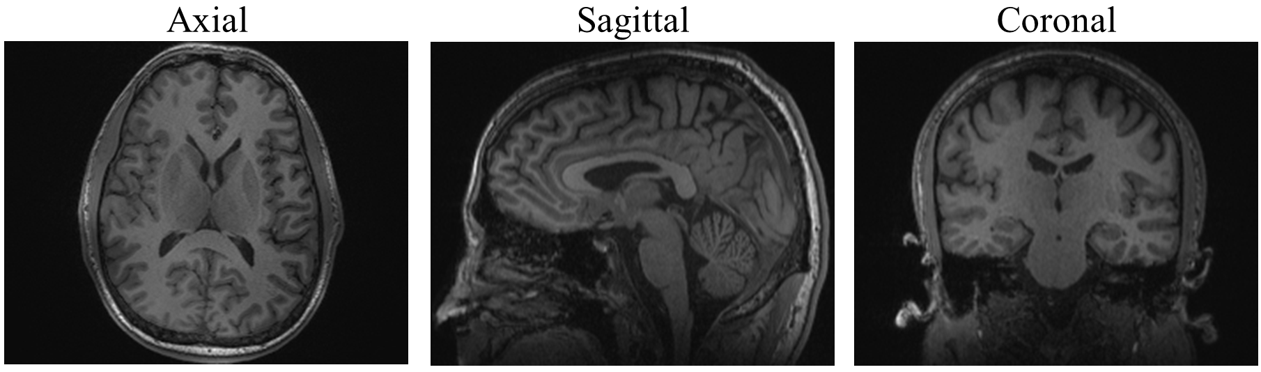
1H: In phantom experiments achieving a 90° flip angle with a 500μs hard pulse required 202v. 1H B1+ maps (Fig.4) show that the 17O/1H array caused minimal distortion to the body coil transmit field. SNR maps (Fig.5) show that at the center of the phantom the Head/Neck 20 array outperforms the 17O/1H array approximately by 20%. 1mm isotropic MPRAGE images (Fig.6) show that the 17O/1H provides adequate uniformity, coverage and SNR.
Conclusions and Discussion
Derangements in oxygen metabolism are fundamental to many pathologic processes. We developed a dual-tuned 17O/1H coil for simultaneous PET/MR on a clinical 3T system. Despite the use of high impedance trap circuits on the 17O elements, the 17O performance was not compromised. Our coil array can potentially facilitate simultaneous 17O-MRI functional issue characterization and PET neuroimaging.Acknowledgements
The authors thank Jerzy Walczyk for his efforts on the coil housings.References
1. C. P. Derdeyn, et al. Brain 2002.
2. R. L. Grubb, Jr., et al. J Neurosurg 2013.
3. W. J. Powers. Ann Neurol 1991.
4. X. H. Zhu., et al. Prog NMR Spectrosc, 2011.
5. D. Kurzhunov, et al. Magn Reson Med 2017.
6. D. Kurzhunov, et al. Neuroimage 2017.
7. S. H. Hoffmann, et al. Magn Reson Med 2011.
8. R. Brown, eat al. Scientific Reports 2016.
9. G. Pipe, et al. Magn Reson Med 2011.
10. H.P Fautz, et al. Proc. 16th Annual Meeting ISMRM, 2008:1247.
11. Q, Duan, et. al. Medical Physics, 2014:41(10); 102303
Figures
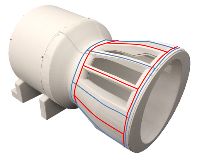
Figure 1. Coil Image.17O- 4 elements, blue. During 17O transmit the coil array works in CP mode(using a 1:4 way power divider and phase shifters). During receive the coil works as a phasedarray.
1H - 8 elements, red. The 1H elements are receive only and the coil operates in phased arraymode.
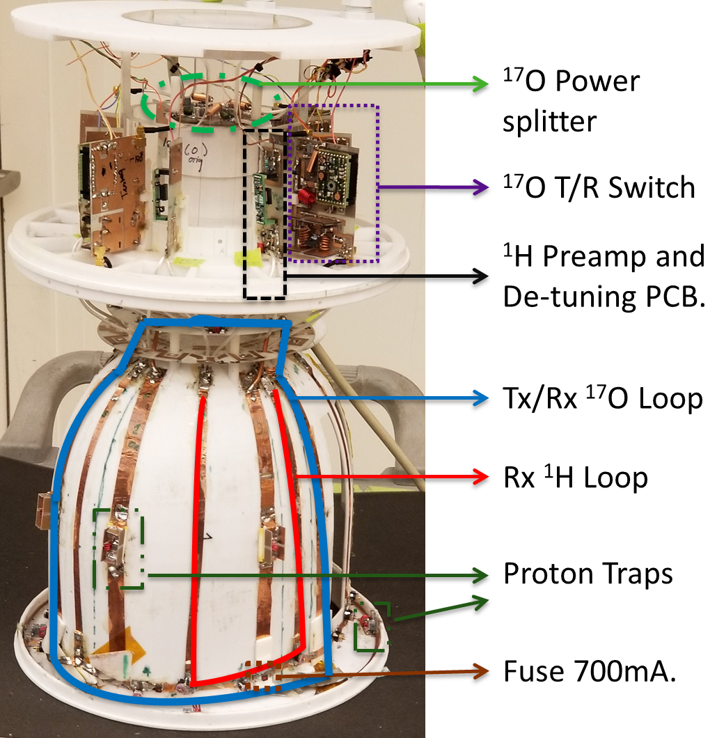
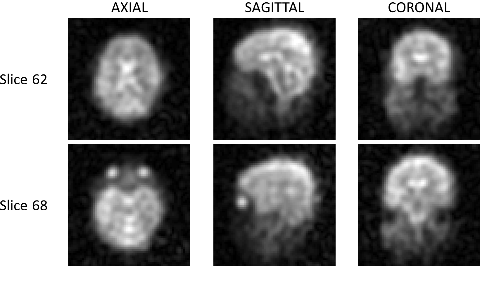
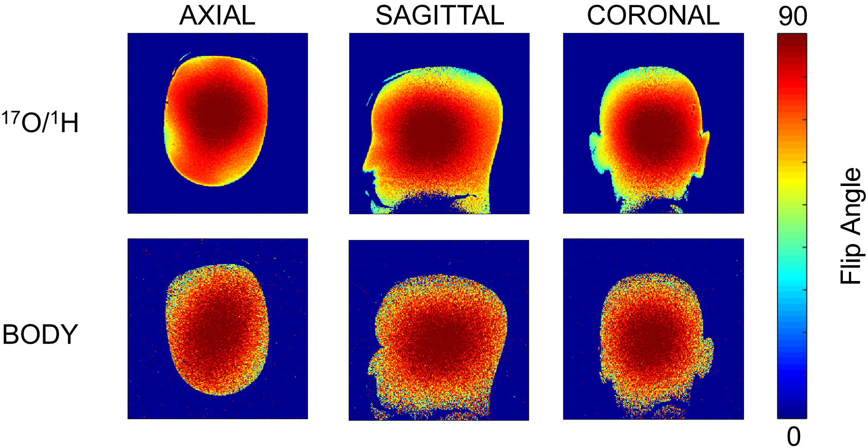
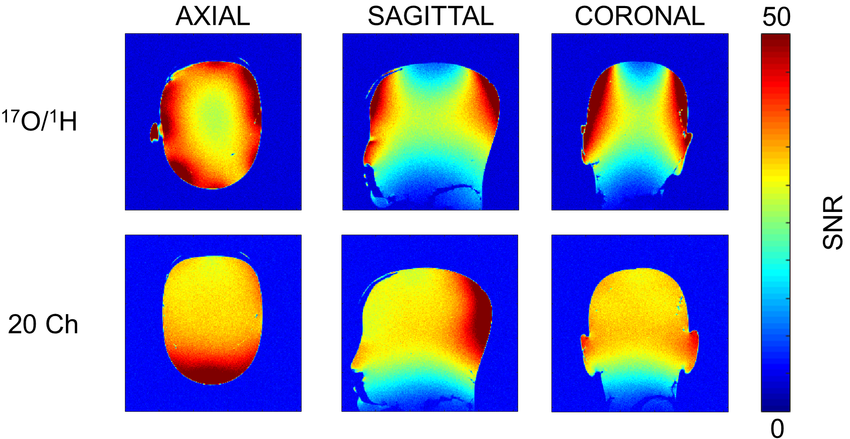
Figure 5. 1H SNR Maps. GRE Sequence (TR/TE/FLIP/BW/Slice 500ms/3.82ms/10o/260Hz/3mm, Matrix 256, FoV 250mm).