1496
Real-time image-based tracking of B0 shim elements in flexible matrix shim arrays for dynamic B0 shimming of the abdomen1Department of Radiology, MR Physics & Instrumentation Group, A.A. Martinos Center for Biomedical Imaging, MGH, Harvard Medical School, Charlestown, MA, United States, 2Division MR Physics, Center for Medical Physics and Biomedical Engineering, Medical University Vienna, Vienna, Austria
Synopsis
High-order matrix shimming has proved useful for addressing B0 susceptibility issues but requires prior knowledge of the shim elements position. For rigid coil formers the shim loops are fixed in space and the field maps can be pre-measured in a phantom. Flexible or movable arrays used in abdominal imaging present a challenge since the element position is patient-specific. Here we introduce a marker system for rapidly detecting the element position prior to or during matrix shimming. Our tests show we can successful determine loop position to accurately generate B0 field maps in good agreement with experimentally measured maps.
Introduction
Large magnetic susceptibility changes between adjacent tissues cause severe spatial B0 variations in the abdomen. It has been shown, in the context of brain and small animal imaging, that this can be corrected using matrix B0 coil arrays, whereby multiple shim loops are driven independently to cancel high spatial frequency B0 variations 1, 2. In ability to pre-calculate the field maps presents a challenge of expanding this technique to flexible, close-fitting arrays for the abdomen. Acquiring a field map of each element is too time-consuming if it must be done on each patient. The problem is confounded further if cardiac and respiratory motion modulates the shim element’s position. In this work, we propose a simple marker-based method to allow tracking of shim element position for fast estimation of the B0 shim profiles in the individual patient and as a function of the respiration and cardiac phases.Methods
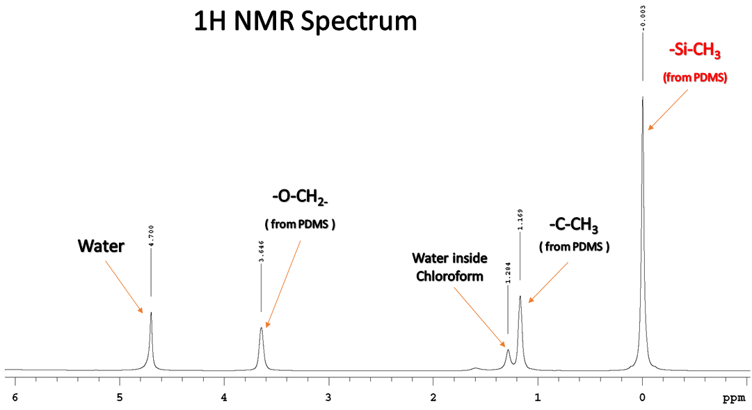
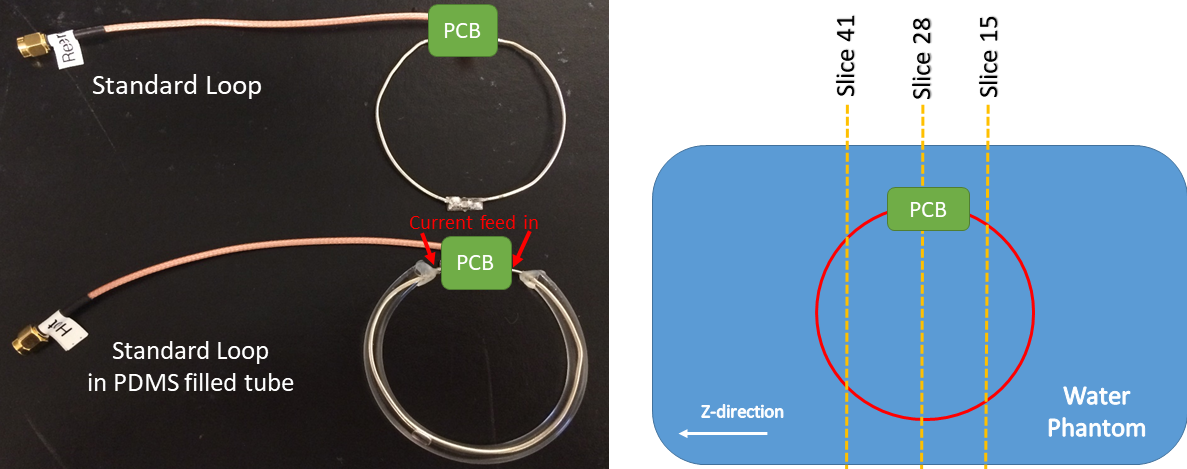
The goal of the method is to render B0 shim loops “MR-visible” by coating them with an MR-visible material. Based on spectroscopic data (500 MHz Varian spectrometer at 25°C), we selected PDMS since this material has a distinct chemical shift of 4.7 ppm below the water peak that is distinct from the lipid peak (i.e., the method is not affected by fat suppression) and allows easy separation of the “loop signal” from the rest of the body (Fig. 1) 3. Our “trackable loop” design is therefore a simple RF receive loop for an “AC/DC coil” of AWG16 copper with 70mm diameter, placed in a transparent soft Polyvinylchloride (PVC) tube filled with about 1ml of PDMS (Fig. 2)
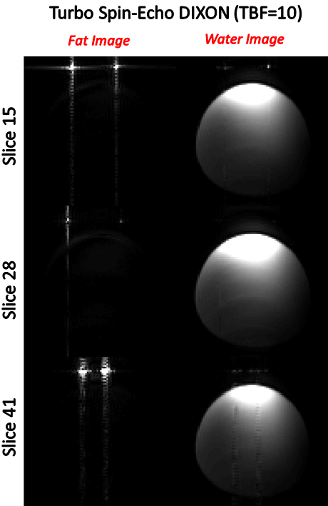
To track the position of the loop, we used a TurboSpinEcho DIXON sequence 4 (TurboFactor (TBF) = 10, TR/TEeff/FA = 5370 ms/12 ms/119°, matrix = 128x128x50, FOV: 256x256x100 mm, SL = 2mm, Tacq = 3:58 min). The TEs were adjusted to produce in/out of phase 3D image volumes corresponding to the water peak (0 ppm) and the PDMS peak (-4.7 ppm).
We extracted the loop trajectory from the PDMS peak image in the image coordinate system and transform to the scanner coordinate system. We then segment the loop signal (thresholding) and reconstruct the loop trajectory using a Skeletonization algorithm 5. The gap created by the PCB is not covered by PDMS and must be estimated in this process. The loop trajectory was registered to the reference position that was used to compute the B0 field map, thus yielding the rigid body transformation parameters to move the B0 field map of that element into the correct “estimate position”.
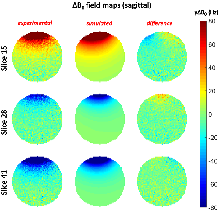
Field maps were estimated using a double-echo gradient echo sequence (transverse, TR/ΔTE/FA = 600 ms/2.46 ms/40°, matrix = 128x128x45, FOV: 256x256x90 mm, SL = 2mm, Tacq = 2:07 min) and while feeding 1A of current into the loop. The body-coil was used for RF transmit and receive, since the loop was detuned due to the current. All scans were performed using a 14cm diameter water-filled tube phantom at 3 Tesla (Siemens MAGNETOM Connectome, Siemens Healthcare, Erlangen, Germany).
Results
Fig. 3 shows the fat/water components extracted from the DIXON data, showing good separation of the loop (PDMS) and phantom (water). Since the Turbo Spin echo DIXON sequence was designed for water-fat separation, the PDMS signal, which is slightly different off-resonance from the lipid signal, was not fully absent from the water image, however the degree of separation is sufficient for automatic extraction of the loop position.
Accurate position estimation of the loop allowed calculation of the B0 field map with good accuracy, as shown in Fig. 4 (difference between measurement and simulation < 10%).
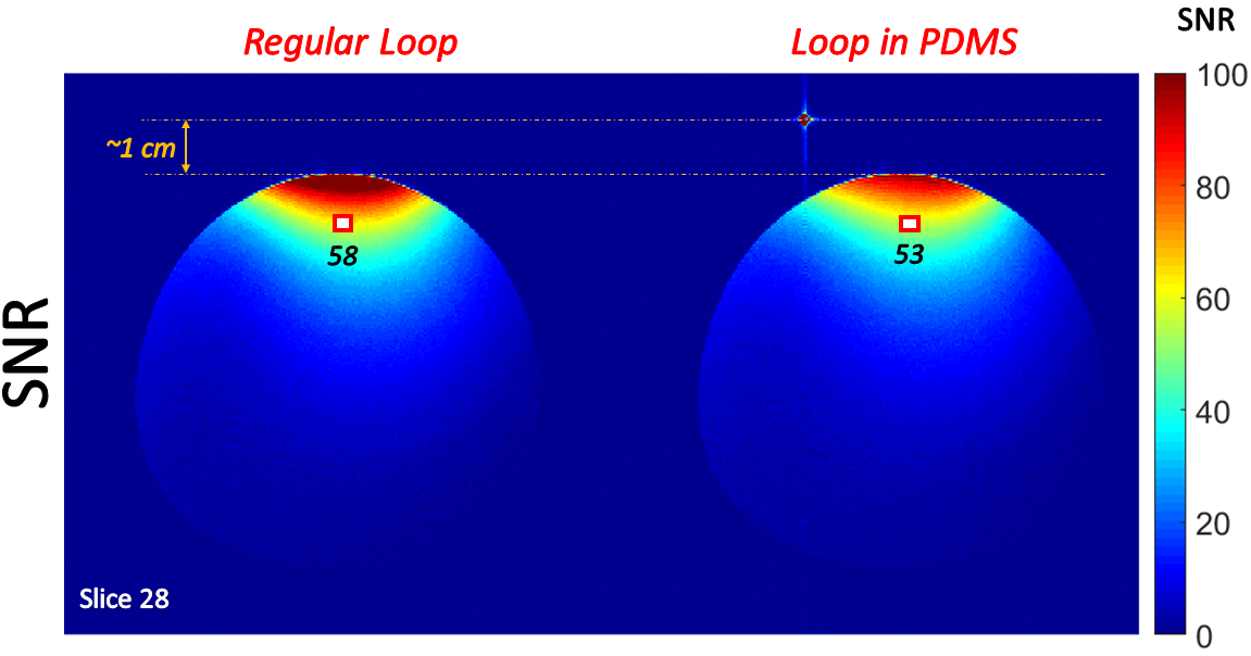
Fig. 5 shows
the SNR produced by the combined shim/RF loop element with and without the PDMS
coating. Adding PDMS around the loop decreased SNR by ~9%.
Conclusion
Our technique allows detection of the loop position in a flexible AC/DC coil with minimal image post-processing. This will be important for determining the shim basis sets in flexible abdominal coils where the array position varies from patient to patient. A limitation of the approach is that Gibbs ringing can occur if the signal level from the PDMS is too high due to the fact that it is so close to the receive loop.
Future work will include a proper implementation of a highly accelerated fat image navigator (3D FatNavs) 6, in order to more efficiently acquire coil-only images (fat or PDMS) using highly undersampled data and L1-norm sparsity constraints, as this kind of image acquisition allows for sparsity constraints. While we chose to put the marker around the loop conductor, other fiducial locations or sparser marker use might be possible.
Acknowledgements
No acknowledgement found.References
- Stockmann JP, Witzel T, Keil B, et al. A 32-channel combined RF and B0 shim array for 3T brain imaging. MRM 2016; 75 (1): 441 - 451
- Juchem C, Nixon TW, McIntrye S, et al. Dynamic multi-coil shimming of the human brain at 7T. JMR 2011; 212 (2): 280 - 288
- Ramli MR, Othman MB, Arifin A, et al. Cross-link network of polydimethylsiloxane via addition and condensation (RTV) mechanisms - Part I: Synthesis and thermal properies. Polymer Degradation and Stability 2011; 96: 2064 - 2070
- Ma J, Choi H, Stafford J., et al. Silicone-specific Imaging using an inversion-recovery-prepared fast three-point DIXON technique. JMR 2004; 19: 298 - 302
- Schindelin J, Arganda-Carreras I, Frise E., et al. Fij: an open-source platform for biological-image analysis. Nature Methods 2012; 9: 676 - 682
- Gallichan D, Marques JP, Gruetter R. Retrospective correction of involuntary microscopic Head movement using highly accelerated fat image Navigators (3D FatNavs) at 7T. MRM 2016; 75: 1030 - 1039
Figures