1491
Enhancement of transmit and receive efficiencies with hybridized meta-atom in 7T head coil1Aix Marseille Univ, CNRS, Centrale Marseille, Institut Fresnel, Marseille, France, 2CEA, DRF, JOLIOT, NeuroSpin, UNIRS, Université Paris-Saclay, Gif sur Yvette, France, 3Multiwave Technologies AG, Geneva, Switzerland, 4ESPCI Paris, PSL Research University, CNRS, Institut Langevin, Paris, France, 5Siemens Healthineers, Saint Denis, France
Synopsis
We show that hybridized meta-atom can be used to improve transmit and receive operation in a 7T head birdcage coil equipped with a 32-channel receive array. Our results demonstrates the enhancement of both transmit and receive signal with the possibility to fill one of the gap usually observed in the brain temporal lobes. This metamaterial based passive shimming strategy provides a cost effective, long-lasting, and non-toxic solution without any impact on the patient’s comfort during the examination.
Background
B1 homogeneity in 7T MRI remains an important challenge in
order to fully benefit from the signal enhancement due to the stronger
magnetization available in ultra-high field scanners. High-dielectric constant pads
have been proposed and optimized for passive shimming purposes1-3. Common formulations of dielectric pads for 7T
applications are based on BaTiO3 mixed with water. They present some
drawbacks such as performance decay over time and toxicity. While previous
studies tackled directly the formulation problem introducing new dielectric
materials and solvent4, we adopted a new approach based on metamaterials5.
We demonstrated that the hybridization of four parallel metallic wires arranged
on a square unit cell provides the ability to control radio frequency field
inside a 7T head birdcage. In the present work, we show that these hybridized
meta-atom (HMA) can be used to improve MRI acquisition in the presence of a
head receive array routinely used for in
vivo MRI protocol.Methods
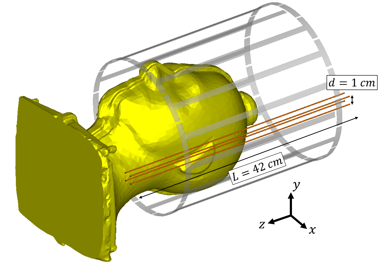
Four 1-mm-diameter brass wires are assembled at the four corners of a 1-cm-side square to form the HMA structure. It is then placed on the left side of the phantom between the birdcage used for transmission and the array used for signal reception. Figure 1 presents a schematics of the arrangement (receive array not shown). MRI acquisition were performed on a specific anthropomorphic mannequin phantom (SPEAG, Zurich, Switzerland) filled with HT0300 liquid (ɛ= 45.3, σ= 0.87 S/m) using a SC72 gradient dedicated 1Tx/32Rx proton head coil (Nova Medical, Wilmington, MA, USA) in a 7T Magnetom MRI scanner (Siemens Healthineers, Erlangen, Germany). Proton density weighted (PDw) images are obtained in the coronal direction with a gradient echo sequence with TR= 5 s, TE= 1.9 ms, FA= 90°, BW= 1563Hz/px, FOV= 256 mm2 on 64x64 pixels (4mm isotropic). Identical parameters were used without any input power to obtain a measurement of noise statistics. Flip Angle (FA) maps are obtained with the XFL MRI Sequence6 in the coronal direction with TR= 20 s, TE= 3.06 ms, FA= 7°, BW=1560 Hz/px for the same FOV and in-plane resolution.Results
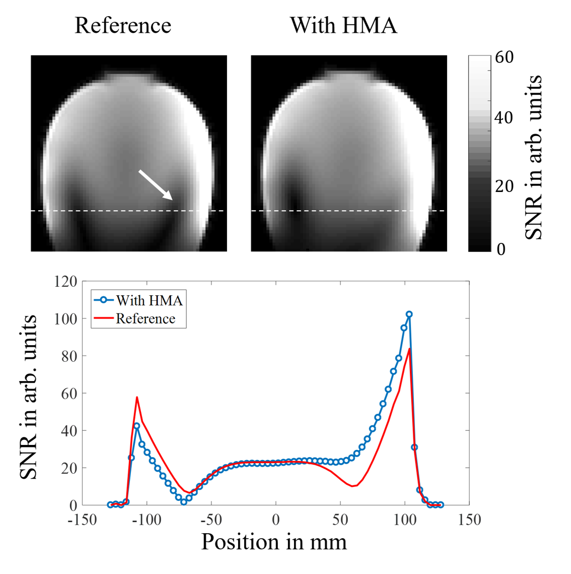
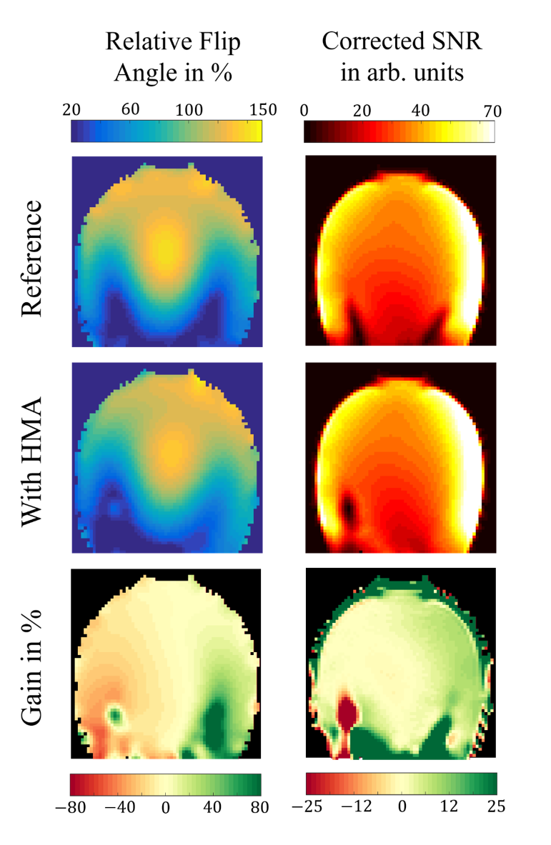
SNR maps are obtained by dividing PDw signal by the standard deviation of noise obtained in 0V acquisition (no input power). Noise standard deviation (in arbitrary units) are 90.2 for the reference and 87.6 in presence of HMA. It is also to be noted that the reference voltage (same in the two acquisitions) was increased by 10% due to the presence of HMA. SNR maps and profile are presented in Figure 2. The profile is taken 8 cm below the center of the slice where the reference case is strongly perturbed. FA maps are obtained and used to calculate the corrected SNR (cSNR) with the following expression $$$cSNR = SNR / sinFA$$$. This correction allows to evaluate the SNR gain in reception as the contribution from the FA distribution is removed. FA maps and cSNR maps are shown in Figure 3. We also present ratios between the maps obtained before and after introducing the HMA.Discussion
SNR maps obtained in Figure 2 show an enhancement at the surface close to the position of the HMA. The main benefit concerns the lower part of the phantom where strong inhomogenities are observed with the reference case. After introduction of the HMA, one can observe that the SNR remains constant over 10 cm, closing the gap initially observed between the surface and the center of the phantom. FA maps and cSNR presented in Figure3 help to understand the origin of such an improvement. We show that while the HMA influences the FA distribution allowing us to excite areas that would have remain dark otherwise, it also has a strong influence on the reception of the signal. Results show a drastic improvement in terms of transmission efficiency (2-fold) and cSNR (3-fold) in the gap originally observed close to the HMA location. Meanwhile, an averaged improvement (+15 %) in FA magnitude and cSNR is observed over a wide area corresponding to the left half of the phantom.Conclusion
These results show that the HMA structure is perfectly compatible with a birdcage equipped with a receive array. It has the ability to enhance both transmit and receive signal with the possibility to fill one of the gap usually observed in the brain temporal lobes. This metamaterial based passive shimming strategy provides a cost effective, long-lasting, and non-toxic solution without any impact on the patient’s comfort during the examination. Future work will target the global homogenization of FA and SNR in the whole brain with the use of multiple elements.Acknowledgements
This work has received funding from the European Union Horizon 2020 Research and Innovation program under Grant Agreement No. 736937.References
1A. G. Webb, Concepts Magn. Reson. (2011)
Part A 38A, 148
2T.
P. A. O’Reilly, A. G. Webb, and W. M. Brink, J. Magn.
Reson. (2016)
270, 108-114
3A. L. Neves, et al., Magn. Reson. Med. (2018) 79, 1753
4Z. Raolison, et al., Proc. Intl. Soc. Mag. Reson. Med., Paris, France (2018) 26, 2664
5M. Dubois, et al., Phys. Rev.
X (2018)
8, 031083
6A. Amadon, F. Mauconduit, A. Vignaud, and N. Boulant, Proc. Intl. Soc. Mag. Reson. Med., Toronto, Canada (2015) 23, 2377
Figures