1490
Stretchable and Flexible Conductive-Thread Based Radiofrequency Coils for Magnetic Resonance Imaging1Weldon School of Biomedical Engineering, Purdue University, West Lafayette, IN, United States, 2Basic Medical Sciences, Purdue University, West Lafayette, IN, United States, 3School of Electrical & Computer Engineering, Purdue University, West Lafayette, IN, United States
Synopsis
An omnidirectional stretchable and flexible radiofrequency coil has been developed using conductive thread stitched onto athletic material. This single-loop surface coil can be placed at the closest proximity to the skin. When compared to a flexible, copper-clad printed circuit board coil, resulting MR FSE images of a muscle phantom showed comparable SNR and image quality, especially when compared to a PCB coil spaced 4.2 cm above the phantom. This design allows not only for close proximity of placement to the skin, but also for joint imaging at various degrees of flexion and positioning.
Introduction
In order to enhance the signal-to-noise ratio (SNR), radiofrequency (RF) receive coils are oriented to surround the anatomical area of interest. However, these coils are often limited to a set size range that may not facilitate the closest proximity fit and maximize SNR. Advances have been made in the creation of bendable RF coils, some with limited stretching capabilities, but there is still room for improvement. Here we present an omnidirectionally stretchable, stitched, conductive-thread RF coil that allows for a completely custom fit at the closest placement to the skin.Methods
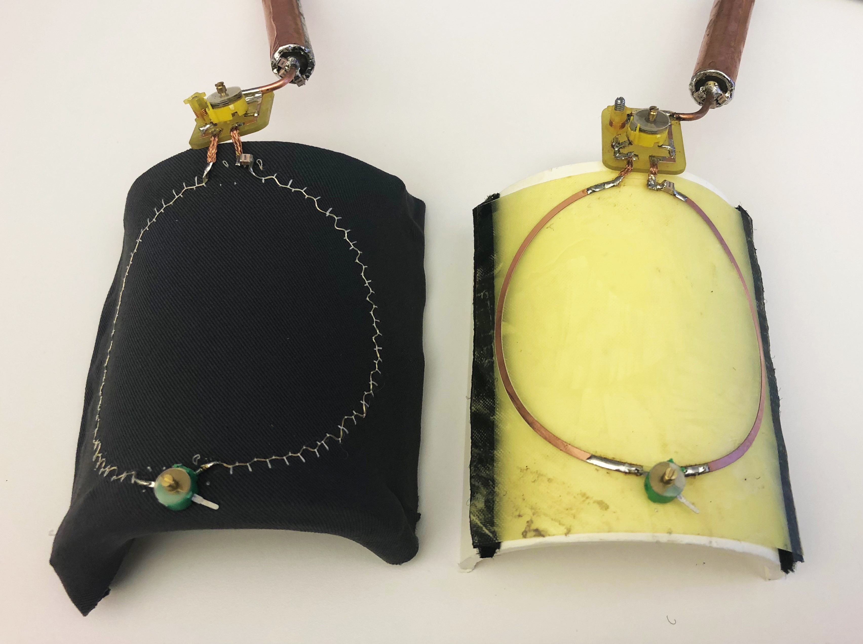
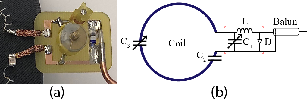
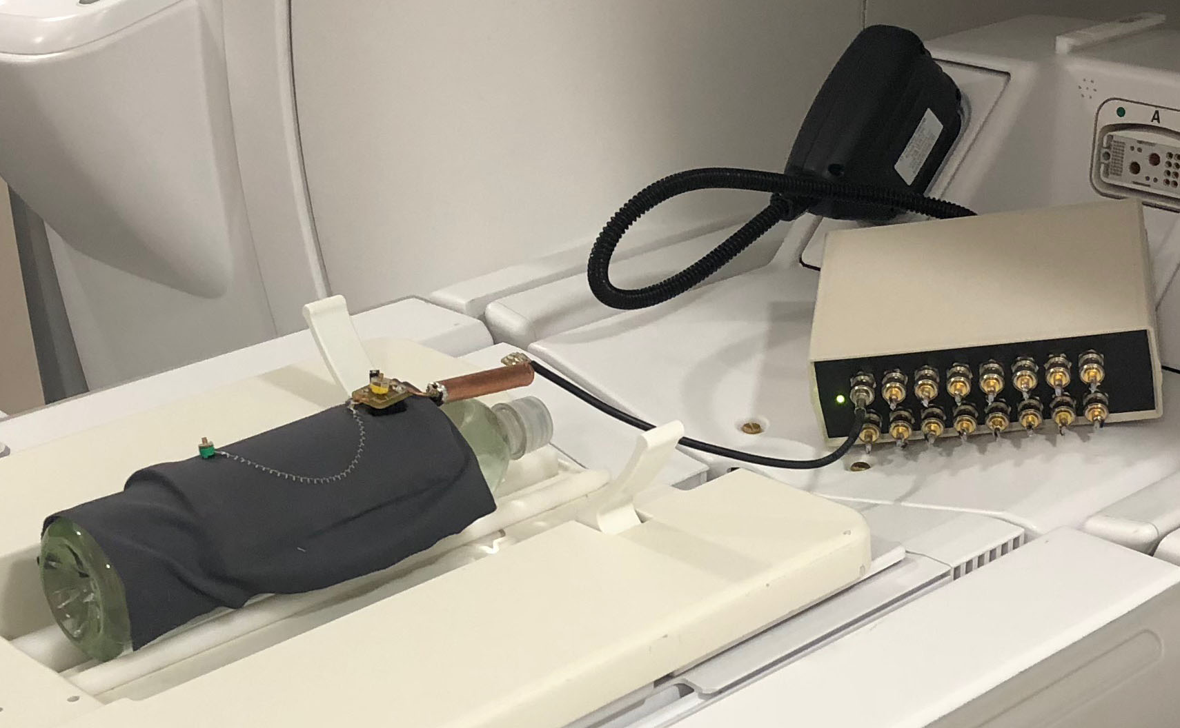
Lyofil (Syscom Advanced Material, OH, USA) fiber was stitched into two 71-mm single-loop receive coils on an athletic fabric (composition: 90% polyester and 10% spandex), anchored with a 100% polyester bobbin thread, using a zig-zag stretch stitch on a Brother JX517 sewing machine (Brother International Corporation, NJ, USA). A comparison coil was milled on 1-oz, 0.18-mm thick, flexible copper-clad FR-4 printed circuit board (PCB) with the same dimensions as the stitched coils. All coils were mounted on a 3-D printed half cylindrical shell with hook and loop fasteners. The stretched coil was mounted so that the coil diameter was increased from 35.5 mm to 42.5 mm. These stitched coils and their mounting can be seen in Fig. 1. Match and tune boards, that also include current traps, were made for all three coils along with baluns. The schematic and image of this board are seen in Fig 2. A vector network analyzer (E5071C, Keysight, CA, USA) was used to tune both the traps and coils to 128 MHz, the Larmor frequency of hydrogen at 3T. Trap tuning was performed with a DC power supply (1685B, B&K Precision Corporation, CA, USA) to forward bias the circuit at 5 V. Once tuned, the coil matching and tuning was verified using a bias of -5 V. Q-factor calculations were completed for both loaded and unloaded measurements, using the S11 method.1 Coil testing and assessment was performed on a 3T whole-body MR scanner (Discovery MR750, GE Healthcare, IL, USA). The coils were individually connected to a receiver gateway box (16xRx, Clinical MR Solutions, WI, USA). All coils were placed on a 1-L phantom with a conductivity of 0.719 S/m and permittivity of 63.5, consistent with dielectric properties of human muscle as defined by the IT’IS Foundation.2 To test coil spacing the PCB coil was also placed 4.2 cm above the phantom with cardboard. A sample scan setup can be seen in Fig. 3. The scan protocol consisted of a fast spin-echo (FSE) sequence with an echo time (TE) of 120 ms, slice thickness of 10 mm, pixel size of 0.7 mm × 0.7 mm, and grid size of 256 × 256. The built-in body coil was used to transmit, as all stitched coils and the PCB coil were receive-only. Scan data were imported into MATLAB (MathWorks, MA, USA) and SNR was calculated using in-house code following the NEMA standards of a 7 × 7 pixel region of signal and 11 × 11 pixel region of noise.3Results
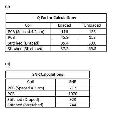
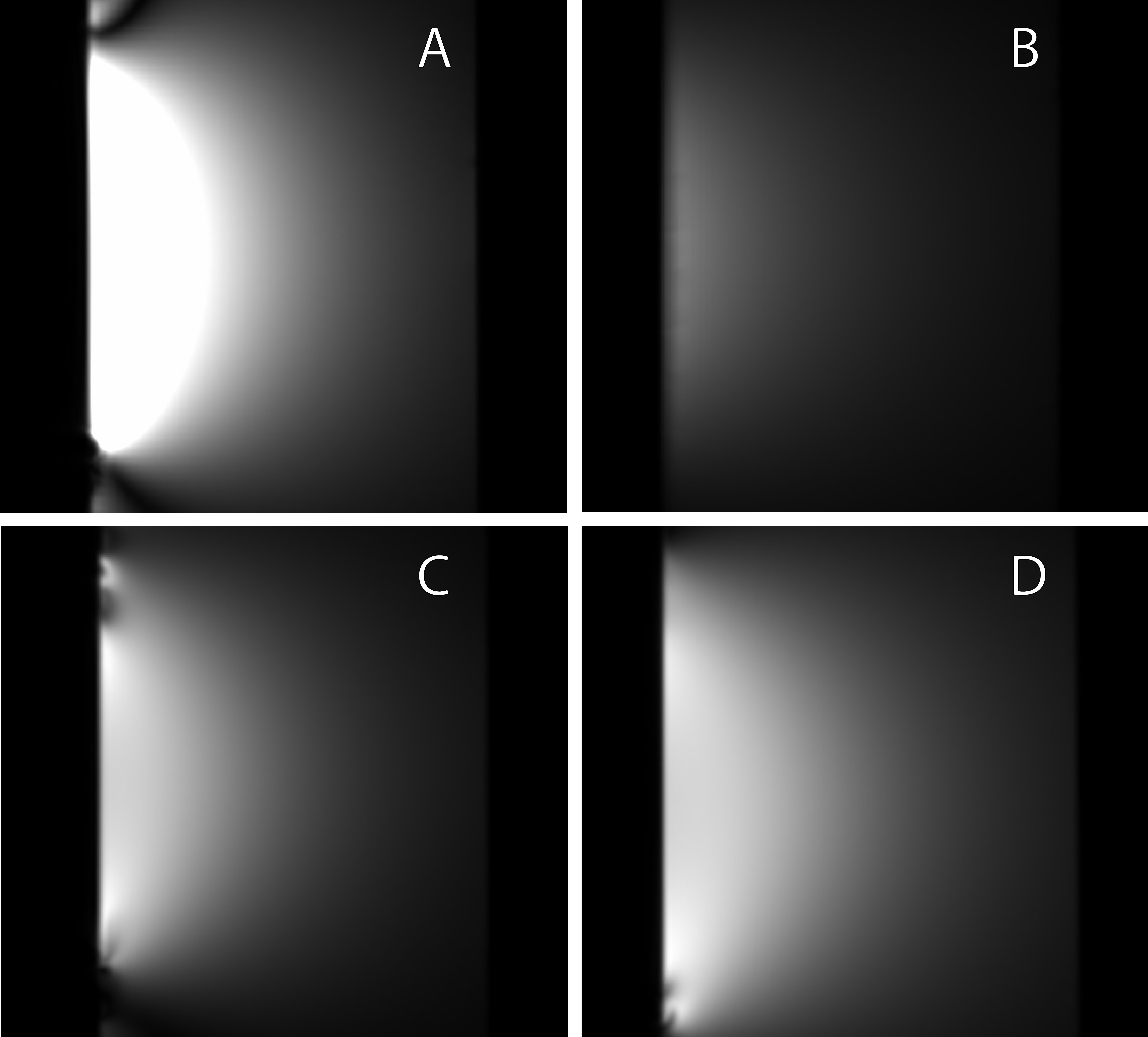
Q-factor and SNR calculations are summarized Fig. 4. Fig. 5 shows the single-slice images acquired from the FSE sequence. All images have the same contrast and brightness for accurate comparison.Discussion
The PCB coil exhibits greater signal value than the stitched coils; however, the SNR value of the stitched, draped coil is similar to that of the PCB coil. The stretched coil did exhibit more noise but this was to be expected because with a larger coil, there is a larger total noise volume resulting in a lower SNR. Comparison between the flux densities, B1, show that they were proportional to the loaded SNR measurements. The Q-factor and SNR calculations for the PCB coiled spaced 4.2 cm above the phantom are important in illustrating that proximity of the coil to the skin affects image quality, as illustrated by the lessened signal in the MR image and SNR calculation. It is also important to note that the spaced PCB Q-factor was higher than that of the stitched coils in the draped and stretched configurations, but yielded a lower SNR.Conclusions
A coil with flexibility and omnidirectional stretching allows for not only a close placement to the skin, but also for imaging joints at various degrees of flexion or positioning. This also provides increased patient comfort and customized fit. These stretchable coils are well-suited for joint imaging and could also be applied for breast or brain imaging.Acknowledgements
We would like to thank Dr. Gregory Tamer, Jr. for his assistance with MR scan setup and guidance.References
1. Doty FD, Connick TJ, Ni XZ, Clingan MN. Noise in high-power, high-frequency double-tuned probes. J Magn Reson. 1988;10.1016/0022-2364(88)90011-X.
2. Hasgall PA, Di Gennaro F, Baumgartner C, et al. IT’IS Database for thermal and electromagnetic parameters of biological tissues, Version 4.0, May 15, 2018;10.13099/VIP21000-04-0. http://itis.swiss/database.
3. NEMA-MS-6. Determination of Signal-to-Noise Ratio and Image Uniformity for Single-Channel Non-Volume Coils in Diagnostic MR Imaging. NEMA MR Standards: MS 6-2008 (R2014). Rosslyn, VA: National Electrical Manufacturers Association, 2015.
Figures