1488
MR vessel wall imaging of intracranial and carotid arteries with a 40-channel coil system at 3 T1Lauterbur Imaging Research Center, Shenzhen Institutes of Advanced Technology, Chinese Academy of Sciences, Shenzhen, China, 2Shanghai United Imaging Healthcare, Shanghai, China, 3Department of Radiology and Biomedical Imaging, University of California San Francisco, San Francisco, CA, United States, 4UCSF/UC Berkeley Joint Graduate Group in Bioengineering, San Francisco, CA, United States
Synopsis
Due
to the small cross-sectional size of the vessel wall and the cord, and
susceptibility effects, especially in the carotid and the spinal cord, MR
vessel wall imaging of intracranial and carotid arteries still remains challenging. In this
work, a 40-channel coil system that consists of a 32-channel head coil combined
with an 8-channel carotid coil was implemented and characterized in its
performance by comparison with a 24-channel head and neck joint coil. As a
result, the proposed 40-channel coil system provides improved performance in
SNR, parallel imaging capability, and image quality.
Introduction
Atherosclerotic plaque is the mainly cause of ischemic stroke1. For plaque detection, simultaneous intracranial and extracranial arterial wall imaging would greatly enhance the convenience of clinical diagnosis. Due to the low SNR and a high spatial resolution requirement, vessel wall imaging is challenging. Previous studies showed that a high isotropic spatial resolution of 0.6 mm can be achieved by using a 32-channel coil system including a 24-channel head coil and an 8-channel carotid coil2. In this work, we have designed and built a 40-channel coil system with a 32-channel head coil and an 8-channel carotid coil for MR vessel wall imaging at a 3 T MRI system (uMR 790, Shanghai United Imaging Healthcare, Shanghai, China). The coil performance was characterized with improved SNR, enhanced parallel imaging capability, and superior image quality in human studies, compared to a commercially available 24-channel coil array with a 17-channel head coil and a 7-channel neck coil.Methods
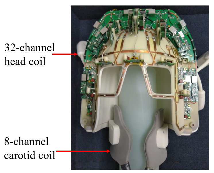
The layout of the 40-channel coil system is shown in Fig. 1. Here, the decoupling methods of employing low input-impedance preamplifiers were applied between the head coil array and the carotid coil array. Each element was tuned to 128.23 MHz and 50 ohm impedance-matched to minimize the noise of the preamp.
The human studies were IRB approved, and informed consents were obtained from all subjects. The human images covering the head and the neck in the sagittal and coronal planes were acquired with a 2D GRE sequence (TR/TE=300 ms/10 ms, flip angle=30o, slice thickness=5 mm, FOV= 300 mm x 200 mm, Matrix size=256 x 234), and the noise images were acquired with the same sequence when flip angle=0o. For the transverse planes of the head and neck, FOV was set as 200 x 200 mm2 and 150 x150 mm2, respectively, and matrix size was respectively set as 256 x 256 and 128 x 128. The signal and noise results can be applied to compute covariance weighted SNR and SENSE g-factor map3. For MR vessel wall imaging, a modified 3D MUST-MATRIX (MUST: Motion induced attenutation by Unbalanced STeady-state free precession preparation; MATRIX: Modulated flip Angle Technique in Refocused Imaging with eXtended echo train) sequence was applied with parameters: TR/TE=850 ms/14.7 ms, echo train length=40, FOV=212 mm (S-I) x 192 mm (L-R), slice thickness=0.6 mm, slices=240, matrix size=336 x 304, Bandwidth=600 Hz/Px, accelerate factor=3.5. Fat suppression was applied in the sequence. The scan of intracranial and extracranial arterial wall took 7.7 min with an isotropic spatial resolution of 0.63 mm x 0.63 mm x 0.6 mm.
Results
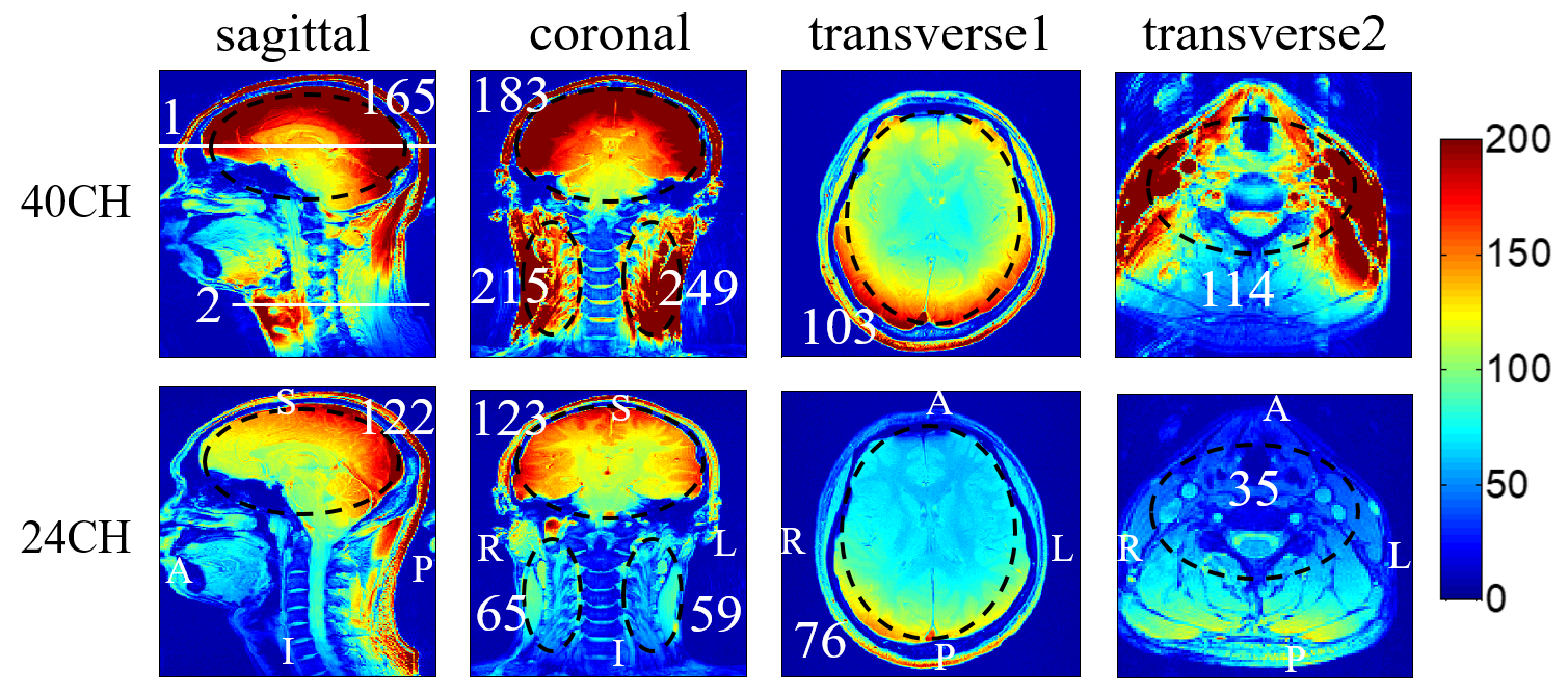
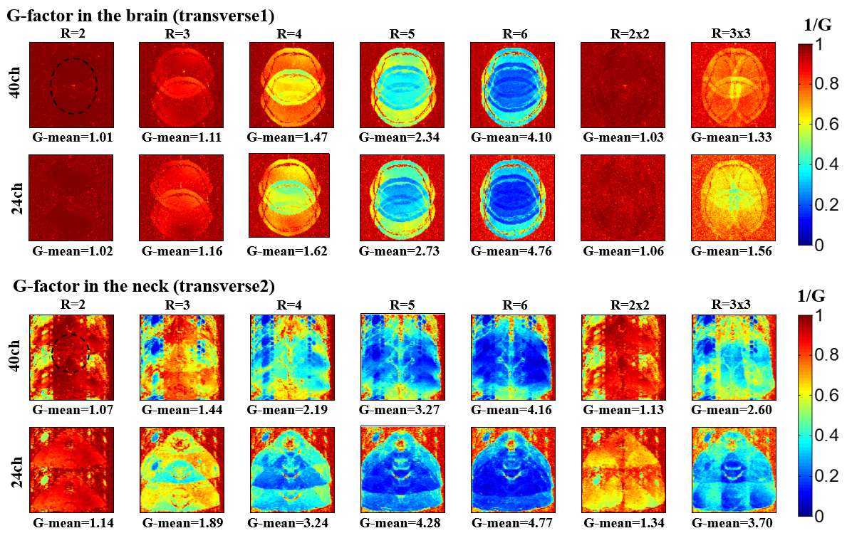
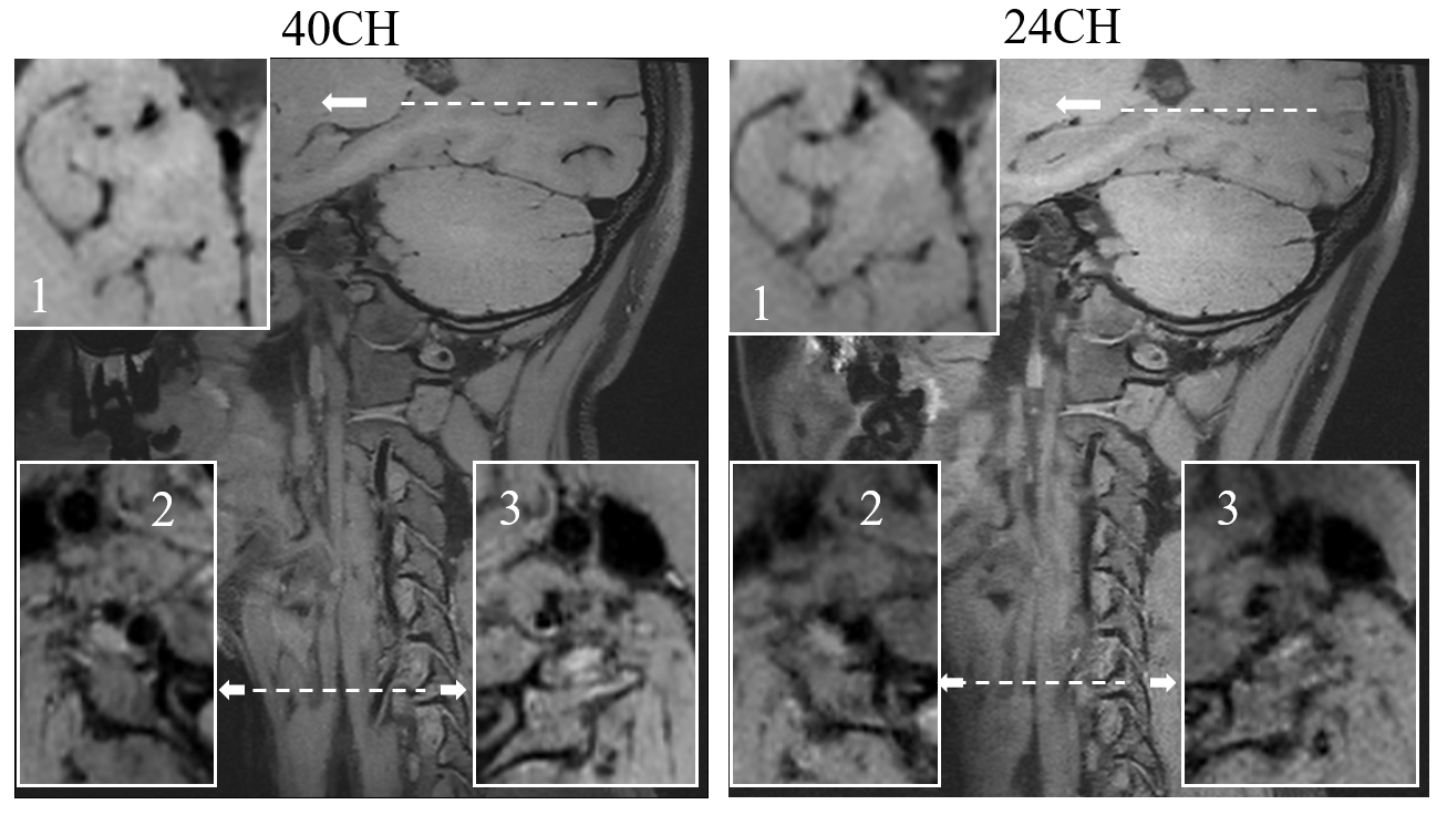
The SNR distributions of human images in the transverse, sagittal and coronal planes are showed in Fig. 2, from which it can be known that the 40-channel coil system has achieved at least 35% SNR improvement in the region of interest (ROI) as compared to the 24-channel coil. Fig. 3 depicts the inverse g-factor maps in the two transverse planes of the head and neck regions with acceleration factors from 2 to 6 in the Right/Left (R/L) direction and R=2x2, R=3x3. Obviously, the 40-channel coil system shows a better parallel imaging capability than that of the 24-channel coil, particularly at high acceleration factors. The MR vessel wall images of intracranial and carotid arteries are illustrated in Fig. 4. In the figure, transverse images of local FOV are also depicted, from which it can be known that the vessel walls of carotid arteries are more clearly visualized by using the 40-channel coil system.Conclusion
A 40-channel array coil system for MR vessel wall imaging of intracranial and carotid arteries was designed, constructed and evaluated by imaging experiments in human studies. Compared to a commercial 24-channel head and neck joint coil, the 40-channel coil system achieves better performance in MR SNR, acceleration capacity and quality of MR vessel wall images.Acknowledgements
This work was supported in part by NSFC under Grant No. 61571433, 61801466, 81627901, 81527901; Guangdong Province grants 2014A030312006, and 2014B030301013; Youth Innovation Promotion Association of CAS No. 2017415; city grants JCYJ20170413161314734; NIH U01EB023829, and a Pengcheng Scholar Award.References
1. A. I. Qureshi, L. R. Caplan. “Intracranial atherosclerosis,” Lancet, vol.383, no.9921, pp.984-998, Mar. 2014.
2. X. Hu, Y. Li, L. Zhang, X. Zhang, X. Liu, and Y. C. Chung. “A 32-channel coil system for MR vessel wall imaging of intracranial and extracranial arteries at 3T,” Magnetic resonance imaging, vol.36, pp. 86-92, Feb. 2017.
3. B. Keil, and L. L. Wald. “Massively parallel MRI detector arrays,” Journal of magnetic resonance, vol.229, pp. 75-89, Apr. 2013.
Figures