1487
High-Q, tunable High Temperature Superconducting receiver coil for 13C applications1Technical University of Denmark, Kgs. Lyngby, Denmark
Synopsis
Dissolution DNP has emerged as a technique to improve SNR in an NMR experiment with inherent limitation of polarization retention in solution ranging, in general, from 30 to 100 s for the interesting bio-molecules. The limitation in sensitivity and available time window can be, however, improved by a better SNR of the RF receivers. At 3 T the Larmor frequency of the 13C nuclei is 32.13 MHz, which is still in the electronics noise dominated regime for smaller coils. A High-Temperature Superconducting (HTS) receiver coil with high-Q, remotely tunable, detunable and compatible to standard electronics Tin soldering has been developed for MRI 13C applications.
Introduction
Increasing the SNR in a single coil under electronics noise dominated regime can be achieved by increasing the Q factor of the receive coil and minimizing the amplifier current and voltage noise spectral densities. Several limitations related to the practical implementation of HTS coils were overcome in this design by the use of varactors for electronically tuning the coils, a new PIN diode detuning scheme compatible with cryogenic temperatures and an inductively coupled receiver to keep the amplifier out of the liquid nitrogen.Methods
An HTS coil consisting of 3 turns spiral with 1 mm trace width, 2 mm gap between traces, gold-platted soldering pads and SiO2 coating as a protection layer for the YBCO traces has been used for the receiver (CERACO Ceramic Coating GmbH) – see Figure 1. A Copper trace is soldered to the HTS terminals by the use of low temperature In97Ag3 soldering and the Copper terminals are connected to the tuning and detuning circuits by the use of standard Tin soldering. A Copper coil with the same external diameter was built to be used as a reference coil for the SNR comparison, consisting of a coil with a Q factor of approximately 320. The HTS coil is positioned inside a Styrofoam box, used as a Cryostat, at a fixed distance from the sample and its temperature is kept at 77 K by immersing it into liquid nitrogen. An inductively coupled receiver loop coil connected to the amplifier with approximately 40 mm diameter was used, separated by 10 mm from the HTS coil and connected through a series capacitor to the amplifier input. The SNR values are obtained from exciting the receiver coil with the magnetic field generated in a pickup loop, positioned at a distance of 60 mm from the receiver and excited by an external low phase noise RF generator (Rohde & Schwarz, SMC100) operating at a power level of -100 dBm. Spectrum analyzer (Agilent Technologies, E4440A) measurements were taken on the output of the amplifier and the power spectrum density was measured in a 1 Hz resolution bandwidth with 4000 points acquisition and a span of 1 kHz at a center frequency of 32.13 MHz. High-Q, non-magnetic varactor diodes (Skyworks Solutions, Woburn, USA) were used in parallel to the tuning capacitor to allow the fine tuning of the receiver within 5 pF range, which for the mentioned application corresponds to approximately 400 kHz tuning range. A low noise amplifier (WMA32C, WantCom, Chanhassen, USA) was used for the inductive coupling and the schematic of the circuit is shown in Figure 2.Results and discussion
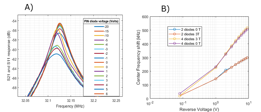
The SNR measurements for both the HTS and Copper coils are presented in the spectrum shown in Figure 3. An SNR improvement factor of 3.6 has been measured, of which a factor of approximately 1.8 can be attributed to the higher Q factor of the HTS receiver coil and a factor of 2 can be attributed to the lower current and noise voltage levels of the pre-amplifier operating at lower temperatures. The center frequency shift as function of the reverse voltage applied to the tuning varactors has been measured and characterized at a B0 field of 3 T. The results are shown in Figure 4 and at a 400 kHz tuning range a 10% Q factor variation within the range was measured. Figure 4 shows how the Q factor changes as function of the center frequency tuning of the resonator. The Q factor of the HTS coil and the varactors Q factor have been tested in a 3 T MRI scanner (3T Philips Achieva MRI scanner, Danish Research Centre for Magnetic Resonance) as function of its orientation relative to a B0 field up to 3 T, and significant field dependence could be identified for angles higher than approximately 30 degrees between the HTS plane and B0 orientation. An ON-OFF isolation of 70 dB was obtained on the PIN diode circuit, and the Q factor as function of the reverse voltage applied to the PIN diodes is shown in Figure 5.Conclusion
Cryogenically cooled HTS coils has been developed and tested at 32.13 MHz, demonstrating an electronically tunable and detunable high temperature superconducting receiver coils at a Q factor that is 4 times higher than what is obtained with Copper coils at room temperature and which can significantly improve the receiver SNR in an electronics noise dominated application. A coil that is compatible to standard electronics Tin soldering techniques was developed and it is foreseen to extend its use to arrays of superconducting coils by the use of cryogenic low impedance amplifier and coil arrays decoupling techniques.Acknowledgements
This work was supported in part by the Danish National Research Foundation.References
1. Black R, Early T, Roemer P, Mueller O, Mogro-Campero A, Turner L, et al. A high-temperature superconducting receiver for nuclear magnetic resonance microscopy. Science (80- ). 1993 Feb 5;259(5096):793–5.
2. Ardenkjær-Larsen JH, et. al. Increase in Signal-to-Noise Ratio of < 10,000 Times in Liquid-State NMR. Proc Natl Acad Sci U S A. 2003;100(18).
3. J. R. Miller, S. E. Hurlston, Q. Y.Ma, D. W. Face, D. J. Kountz, et. al. Performance of a High-Temperature Superconductin Probe for In Vivo Microscopy at 2.0 T. Magnetic Resonance in Medicine, 1999; 41 (72-79).
Figures