1484
Dipole antenna for rat spinal cord imaging at ultra-high field1CIBM-AIT, École polytechnique fédérale de Lausanne, Lausanne, Switzerland, 2Department of Biomedical Engineering, King’s College London, London, United Kingdom
Synopsis
Dipole antenna designs were introduced to pre-clinical spinal cord imaging at ultra-high field. The tuning and matching circuit can be adapted to both 9.4 T and 14.1 T magnet with simple adjustment. Dipole antennas provided good longitudinal coverage for the animal, and optimal penetration for spinal cord imaging. In terms of transmit efficiency and field homogeneity over rat spinal cord, dipole antenna design is a flexible and promising candidate for ultra-high field imaging.
Introduction
Rodent spinal cord imaging at ultra-high field is valuable to assess models of spinal cord injury and recovery with high signal-to-noise ratio and spatial resolution. As spine tissue is close to body surface, surface coils are excellent candidates for high-resolution axial spinal cord imaging, allowing segmentation of spinal cord roots, white/gray matter contrast and characterization (1,2). However, at ultra-high field, B1 field generated from surface coils is highly inhomogeneous along the z axis, traditional surface coil designs would provide limited coverage for the longitudinal direction along the spine. Volume RF coils yields homogeneous MR signal with larger FOV, but with limited spatial resolution due to its lower B1 field efficiency at the spinal cord when imaging at 9.4 T and higher field. Previously, dipole antennas were introduced to be used for transmit/receive coil design at human ultra-high field MRI scanners, and provided superior B1 field homogeneity and penetration for brain and body imaging (3–5). Here in this study, we evaluated the potential of dipole antenna designs for rat spinal cord imaging at 9.4 T and 14 T.Methods
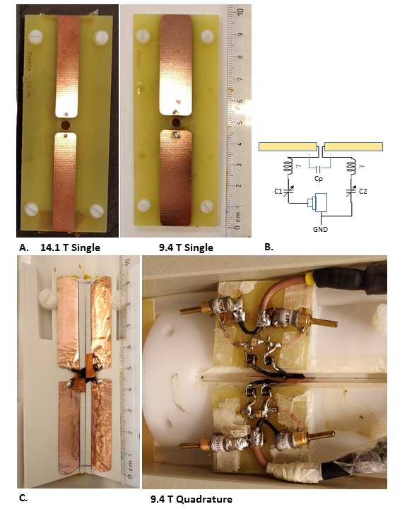
In-house built transmit/receive dipole coils were placed parallel to B0. Coil elements consisted of 100-mm long dipole antenna with thin strip copper conductor (etched on PCB or tape), within a tuning and matching circuit (Fig. 1). Dipole coils were tuned and matched to 400 MHz (9.4 T) and 600 MHz (14.1 T), respectively (400 MHz: inductor L = 12.5 nH, fix capacitor Cp = 0.8 pF; 600 MHz: L = 2.5 nH, Cp = 0.2 pF; range of variable capacitor: 0.1 – 10 pF). To operate as quadrature coil, two dipole antennas were combined with a 100° angle and 4 mm distance in between to avoid coupling (Fig. 1C). All animal experiments were approved by the local animal ethical committee. Rats were directly placed on the coil in supine position for spinal cord scans. To assess the B1 field homogeneity and penetration of single-element dipole coils, 2D gradient echo (0.78×0.47×1 mm3, 128×128 matrix, 60 slices) and fast spin echo (0.12×0.14×1 mm3, 512×256 matrix, 15 slices) protocols were acquired post-mortem. B1 map was calculated from two 2D-GRE images acquired with 60° and 120° flip angle (6). In addition, to delineate spinal cord root structure, in-vivo respiration-triggered high-resolution axial images (FSE, in-plane resolution: 0.078x0.078 mm2, 40 1-mm slices; TA=30 min) were acquired at 9.4 T using a quadrature dipole coil. To accelerate the in-vivo scan, reduced field-of-view was achieved using one coronal saturation band.Results
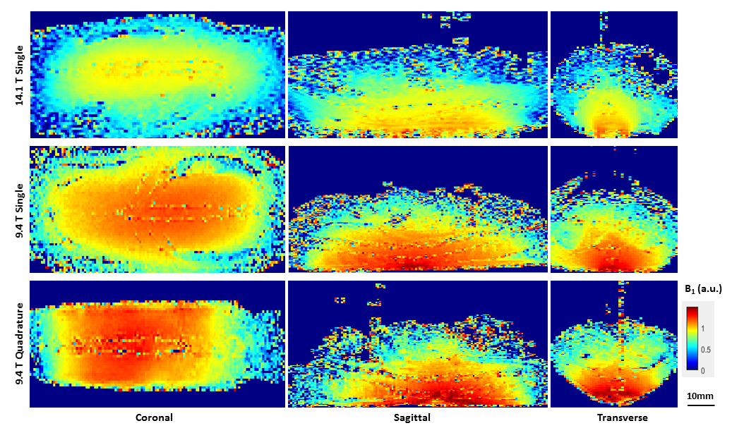
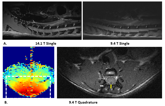
Single dipole antenna showed good performance for B1 field homogeneity along the z-axis at both field strengths (Fig. 2): at 9.4T, global B1 field uniformity along z direction was guaranteed for around 70 mm at the surface, and around 50 mm at the level of rat spinal cord. Due to the shortened wavelength at 14.1 T, B1 field efficiency and its penetration depth is lower compared to the field at 9.4 T. In terms of radial/depth penetration, both coils provided sufficient B1 field efficiency at the level of rat spine, allowing for high-spatial resolution imaging. Meanwhile, the surface design naturally limited the contribution from unwanted abdominal tissue signal (Fig. 3). In 9.4 T quadrature design, combined dipole elements further improved coil efficiency. Due to the special quadrature coil geometry, rat spine was nicely fitted in the center of the coil, which allowed for imaging with smaller FOV. On high-resolution in-vivo images, spinal cord roots, grey and white matter can be reliably segmented in the lumbar region.Discussion and conclusion
Here we demonstrated that dipole antenna design can be adapted for pre-clinical spinal cord imaging at ultra-high field. Dipole antennas provided good longitudinal coverage for the animal, and optimal signal penetration for spinal cord imaging. For studies on 14.1 T magnet, coil tuning and matching efficiency needs to be further improved, and adapted to quadrature mode. To conclude, dipole antenna setup is a promising candidate for imaging fine structure like spinal nerve roots and vascular system in the rat spine, which requires high SNR and spatial resolution.Acknowledgements
Supported by the Centre d’Imagerie BioMédicale (CIBM) of the UNIL, UNIGE, HUG, CHUV, EPFL and the Leenaardsand Louis-Jeantet Foundations.References
1. Budde MD, Xie M, Cross AH, Song S-K. Axial Diffusivity Is the Primary Correlate of Axonal Injury in the Experimental Autoimmune Encephalomyelitis Spinal Cord: A Quantitative Pixelwise Analysis. J. Neurosci. 2009;29:2805–2813.
2. Behr VC, Weber T, Neuberger T, et al. High-resolution MR imaging of the rat spinal cord in vivo in a wide-bore magnet at 17.6 Tesla. Magn. Reson. Mater. Physics, Biol. Med. 2004;17:353–358.
3. Ipek O, Raaijmakers AJE, Klomp DWJ, Lagendijk JJW, Luijten PR, Van Den Berg CAT. Characterization of transceive surface element designs for 7 tesla magnetic resonance imaging of the prostate: Radiative antenna and microstrip. Phys. Med. Biol. 2012;57:343–355.
4. Clément JD, Gruetter R, Ipek Ö. A human cerebral and cerebellar 8-channel transceive RF dipole coil array at 7T. Magn. Reson. Med. 2018:1–12.
5. Raaijmakers AJE, Ipek Ö, Klomp WJ, Possanzini C, Harvey PR, Lagendijk, JJW, van den Berg CAT. Design of a radiative surface coil array element at 7 T: the single-sided adapted dipole antenna. Magn. Reson. Med. 2011;66:1488-97.
6. Stollberger R, Wach P, McKinnon G, Justich E, Ebner F. RF-field mapping in vivo. In: Proceedings of the SMRM, 7th Annual Meeting, San Francisco, CA, 1988. p106.
Figures