1482
Overlapped Monolithic Transmission Line Resonator Receiver and B0 Shim Array For Functional Imaging of the Human Temporal Lobe1CMRR, Biomedical Engineering, Psychology, University of Minnesota, Minneapolis, MN, United States, 2CMRR, University of Minnesota, Minneapolis, MN, United States, 3Marquette University, Milwaukee, WI, United States
Synopsis
Transmission Line Resonator (TLR) coils have been employed and evaluated as simultaneous RF Tx/Rx and B0 shimming elements. However, overlapped variants of these designs which target specific brain regions have yet to be attempted. Here, we have developed an overlapped TLR Rx/B0 shimming array targeted for imaging the temporal lobe at 7T. Bench testing and simulation results demonstrate the feasibility and benefits of an overlapped TLR Rx/B0 shimming array for targeted imaging of targeted brain structures.
Objective
Functional MRI data acquired using high field systems suffers from increases in B0 susceptibility artifacts introduced by a variety of anatomical features, such as air-tissue boundaries in the ear canals and frontal sinuses. Various methods have been developed to combat these issues using either independent, fine-tune B0 shimming arrays1,2, or by implementing inductively choked transmission, reception, and B0 shimming solutions within a single phased array3-5. Recently, that latter concept has been explored using monolithic transmission line resonators (TLRs), which consist of dual sided, gapped wire traces on a dielectric substrate to create a resonant architecture6-8. While the implementation of an Rx/B0 array using a TLR structure has been demonstrated, overlapped variants of these arrays have, to our knowledge, yet to be attempted. Thus, the aim of this work was to explore the expected performance of an overlapped Rx/B0 TLR shimming array. Specifically, we focused on the development of a more limited array targeting the human temporal lobe at 7T.Methods
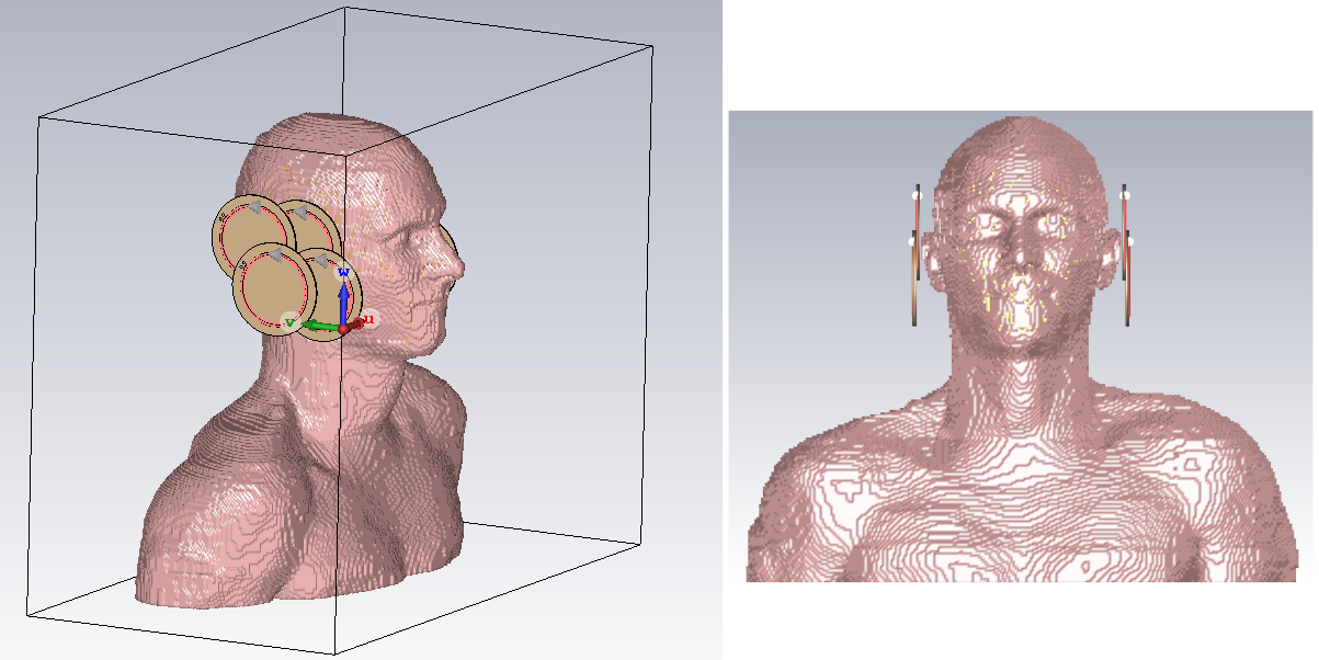
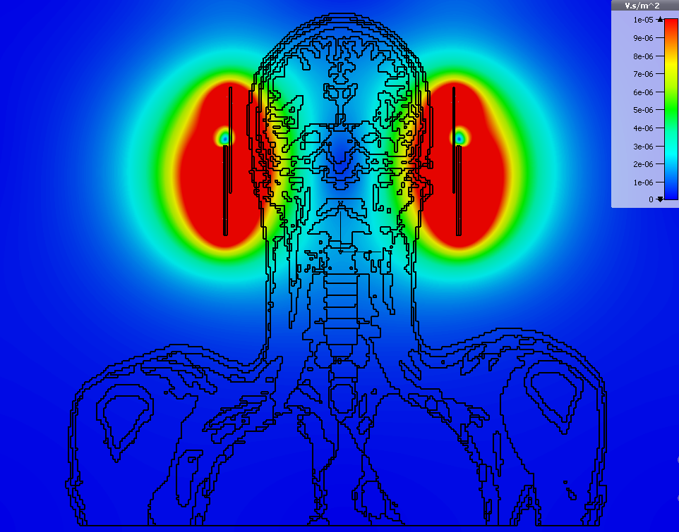
Given our target is the human temporal lobe, a major source of B0 susceptibility artifacts is the air-tissue boundary of the ear canals. Thus, we wanted a design able to selectively shift the field near the ear canals while not disturbing the surrounding field, and to do so with robustness to variation in subject anatomy. Furthermore, we wanted a receive structure that would be able to derive signal from both superficial and deep brain structures of the temporal lobe. As such, we implemented a design using four (7 cm diameter) loops, arranged in a 2x2 overlapped configuration over the temporal lobes (Figure 1). A model was created for magneto-static simulations in CST Studio. The loop elements were positioned approximately 1 cm from the head and approximately optimal spaced to nearest neighbors with a 20 percent area overlap. An initial simulation was performed to determine the magnitude of static magnetic field extending into the temporal lobe region. Each loop element was excited with 1 Amp of current such that the net magnetic field vector pointed away from the head. The resulting magnetic field magnitude is within the desired range of several uT in the region of interest, as shown in Figure 2.
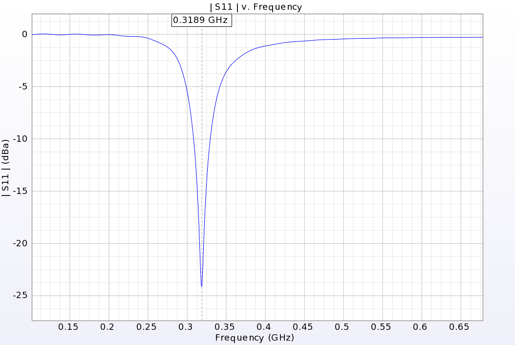
The TLR elements have been modeled and simulated in Remcom XFdtd 7.7. The model was parameterized, allowing quantities such as loop diameter, number of gaps, etc. to be varied. For a desired DC loop diameter of 7 cm, simulations suggested a six segment TLR coil for 7T receiver applications (Figure 3). Figure 4 shows that the six-segment TLR without tune and match circuitry is resonant at 319 MHz when loaded with a phantom (εr=75, σ=0.6S/m approximately one gallon solution of CuSO4 and NaCl in water).
Results and Discussion
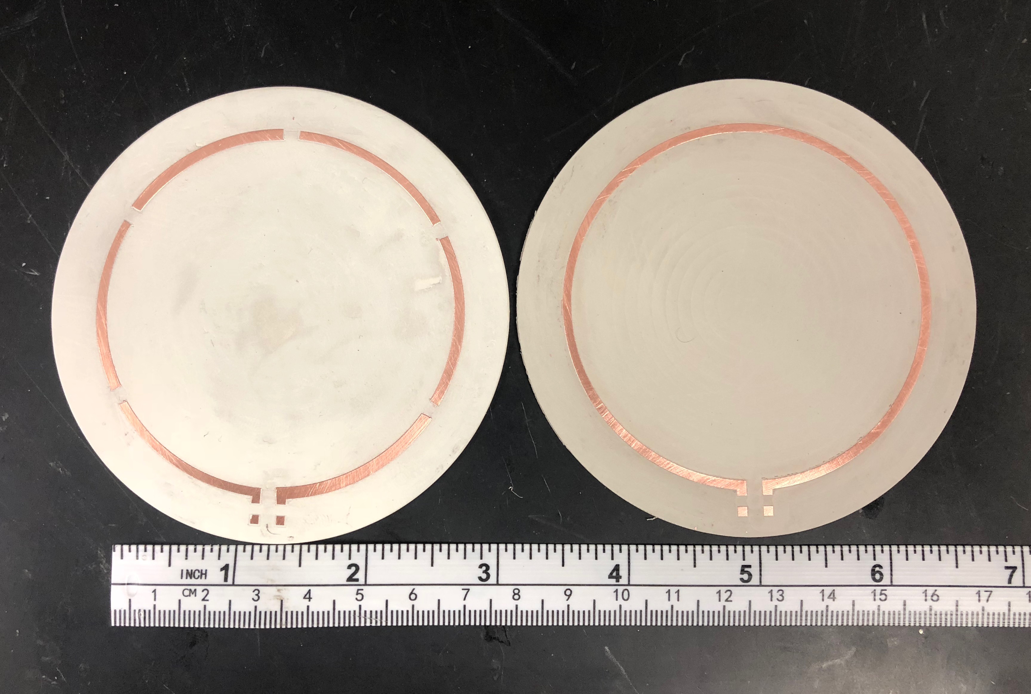
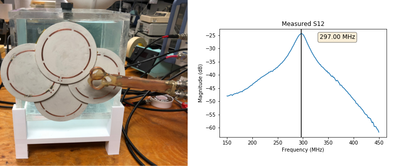
A set of TLR loops were machined out of Rogers R03035, (1oz/sqrt copper, εr=3.5, tan δ = 0.0018) using a Protomat S63 printed circuit board mill. The TLR structure was tested with a Rohde & Schwarz ZNBT vector network analyzer and a decoupled double probe. We were able to adjust the resonance frequency of the machined TLR loops sufficiently with regular tune match circuitry to achieve the target resonance of 297 MHz, as shown in Figure 5. With a set of 4 overlapped loops and 1 A current per loop, our simulations indicate that we can achieve the fields required to adjust for the expected a frequency shift in the temporal lobe of approximately 150 Hz to 200 Hz, translating to a magnetic field shift of approximately 3 uT to 5 uT. In the future we will explore how we can integrate these targeted Rx/B0 arrays into whole head receive arrays.Acknowledgements
P41 EB015894S10
RR026783 “Multichannel Transmit Frontend for 7 Tesla” WM KECK FoundationS10
RR029672 “Console for 10.5 Tesla Whole Body MRI System”
NIH T32 EB008389
NIH T32 EY025187
References
1. J.-J. Hsu and G. H. Glover, “Mitigation of Susceptibility-Induced Signal Loss in Neuroimaging Using Localized Shim Coils,” Magn Reson Med. 2005; 53(2): 243-248.
2. C. Juchem, et. al., “Magnetic Field Homogenization of the Human Prefrontal Cortex With a Set of Localized Electrical Coils,” Magn Reson Med. 2010; 63(1): 171-180.
3. H. Han, A. W. Song, and T.-K. Truong, “Integrated Parallel Reception, Excitation, and Shimming (iPRES),” Magn Reson Med. 2013; 70(1): 241-247.
4. J. P. Stockmann, et. al., “A 32-Channel Combined RF and B0 Shim Array for 3T Brain Imaging,” Magn Reson Med. 2016; 75(1): 441-451.
5. C. Juchem, et. al., “Dynamic Multi-Coil Shimming of the Human Brain at 7 Tesla,” J Magn Reson. 2012; 212(2): 280-288.
6. R. Kriegl, et. al., “Novel Inductive Decoupling Technique for Flexible Transceiver Arrays of Monolithic Transmission Line Resonators,” Mag Reson Med, 2015; 73(4): 1669-1681.
7. R. Frass-Kriegl, et. al., “Multi-Turn Multi-Gap Transmission Line Resonators - Concept, Design, and First Implementation at 4.7 T and 7 T,” J Magn Reson. 2016; 273(1): 65-72.
8. R. Stara, et. al., “Monolithic Transmit Line Resonator as a Combined B1/B0-shim Coil Element,” Proceedings of the 25th Annual Meeting ISMRM, Honolulu, HI, USA, 2017, 0968.
Figures