1481
Preliminary Design Exploration for a Head and Neck Gradient Coil: Effect of Shoulder Cut-out Length on Performance1The xMR Labs, Department of Physics, Western University, London, ON, Canada
Synopsis
A preliminary design study on a shoulder cut-out head and neck gradient coil for improved imaging of the neck was performed. The designs presented here allow a shifted imaging region such that the neck and cervical spine can be placed directly in the imaging region. This work represents the first step in a larger design study and work is still ongoing to determine the effect on gradient coil performance as design parameters are modified. Ultimately, this will allow high performance imaging of both the head and neck.
Introduction
Head and neck imaging continue to account for the majority of all diagnostic MRI scans performed worldwide. However, due to the cylindrical design of traditional compact head-only gradients the neck is situated just outside of the imaging region which provides challenges in imaging the neck and cervical spine. This can be alleviated by lengthening and adding cut-outs to the gradient coil to accommodate the patient’s shoulders while moving the extent of the gradient coil into the cut-out region.1 However, the benefits and trade-offs of adding shoulder cut-outs to the gradient coil on performance is not well explored. Gradient coil performance can be quantified in terms of its efficiency, wire spacing, and imaging region size (among other metrics). Designing a gradient coil with cut-outs can be accomplished using the boundary element method (BEM).2 In this work, our objective was to perform a design study on an actively shielded shoulder cut-out design while exploring the effect of cut-out length on coil performance. We hypothesize that by adding shoulder cut-outs there will be an improvement in performance while allowing imaging of both the head and neck.Methods
Triangular element meshes were designed in, and exported from, COMSOL Multiphysics (COMSOL, Burlington, MA) for analysis in MATLAB (Mathworks, Natick, MA). The exported meshes composed of a primary surface (length = 0.55 - 0.76 m, radius = 0.22 m), a shield surface (length = 1.00 m, radius = 0.26 m) and a bore surface (length = 1.00 m, radius = 0.325 m). The cut-out height (y-direction) was held constant at 0.15 m and the cut-out length (z-direction) was varied for the control coil (no cut-out, length = 0.55 m) and three gradient coils with varying cut out lengths (7 cm (length = 0.62 m), 14 cm (length = 0.69 m), and 21 cm (length = 0.76 m). The BEM method was implemented using custom built MATLAB software aiming for control of field uniformity and minimum wire spacing3 by performing a grid search of weighting parameters resulting in 13500 designs for the X-, Y- gradients and 1350 for the Z- gradient. In this work, the target efficiency was set at 0.10 mT/m/A and all calculated values were scaled to 0.25 mT/m/A while the minimum wire spacing for the X-, Y-, and Z-gradients were chosen as 3.5 mm, 3.5 mm, and 5.5 mm (before scaling), respectively to accommodate realistic manufacturing capabilities. Designs were considered successful for comparison when they met these criteria to enable comparison between each cut-out length for each respective gradient axis. The imaging region was shifted from the isocenter by 0.07 cm and 0.14 cm (along Z) for the control and shoulder cut-out coils, respectively.Results
Examples of X-, Y-, and Z-gradients are shown in Figure 1 and their respective electromagnetic properties are given in Table 1. Contour plots of percent deviation from the center field value are shown in Figure 2, the maximum diameter of a sphere within the 50% line is given as DSV50 in Table 1.Discussion
In this initial explorative design study we have demonstrated that by allowing shoulder cut-outs the imaging region can be shifted providing imaging of the cervical spine in addition to the brain with acceptable impact on system performance. Although the designs presented here provide fields suitable for imaging and have effective shielding (all designs have stray fields at bore surface < 7 mT at 330 A), before a design is chosen for manufacturing there are many things that must be considered.
A final design must be
balanced for forces and torque within the realistic field it will be subjected
to. Furthermore, the effect of cut-out
height on performance parameters must be evaluated as well as broadening the
design study to explore the effects of coil efficiency, imaging region size,
and imaging region offset on the designs. It is clear from Figure 2 and Table 1
that the Y-gradient gains the most benefit from the addition of shoulder
cut-outs as compared to the X, which warrants further investigation into
improving the X-gradient performance. The thumbprint style Z-gradient would
require modifications to the design process as current Z-gradients are wound around
tubing. It would be possible to instead wind cooling lines around the tubing
which would help maintain proper operating temperatures.
Conclusion
We have performed a preliminary design study on an actively shielded shoulder cut-out head and neck gradient coil and demonstrated that regions of cut-out can be added to the gradient surface to allow a shifted imaging region which can facilitate improved imaging of the neck and cervical spine.Acknowledgements
The authors acknowledge financial support from NSERC and the Ontario Research Fund.References
1. Davids, Mathias, et al. Prediction of peripheral nerve stimulation thresholds of MRI gradient coils using coupled electromagnetic and neurodynamic simulations. Magn. Reson. Med (2018).
2. M Poole and R Bowtell. Novel gradient coils designed using a boundary element method. Concepts Magn. Reson., 31B: 162-175 (2007)
3. CT Harris, WB Handler and BA Chronik. Electromagnet Design Allowing Explicit and Simultaneous Control of Minimum Wire Spacing and Field Uniformity. Concepts Magn. Reson., 41B: 120-129 (2012)
Figures
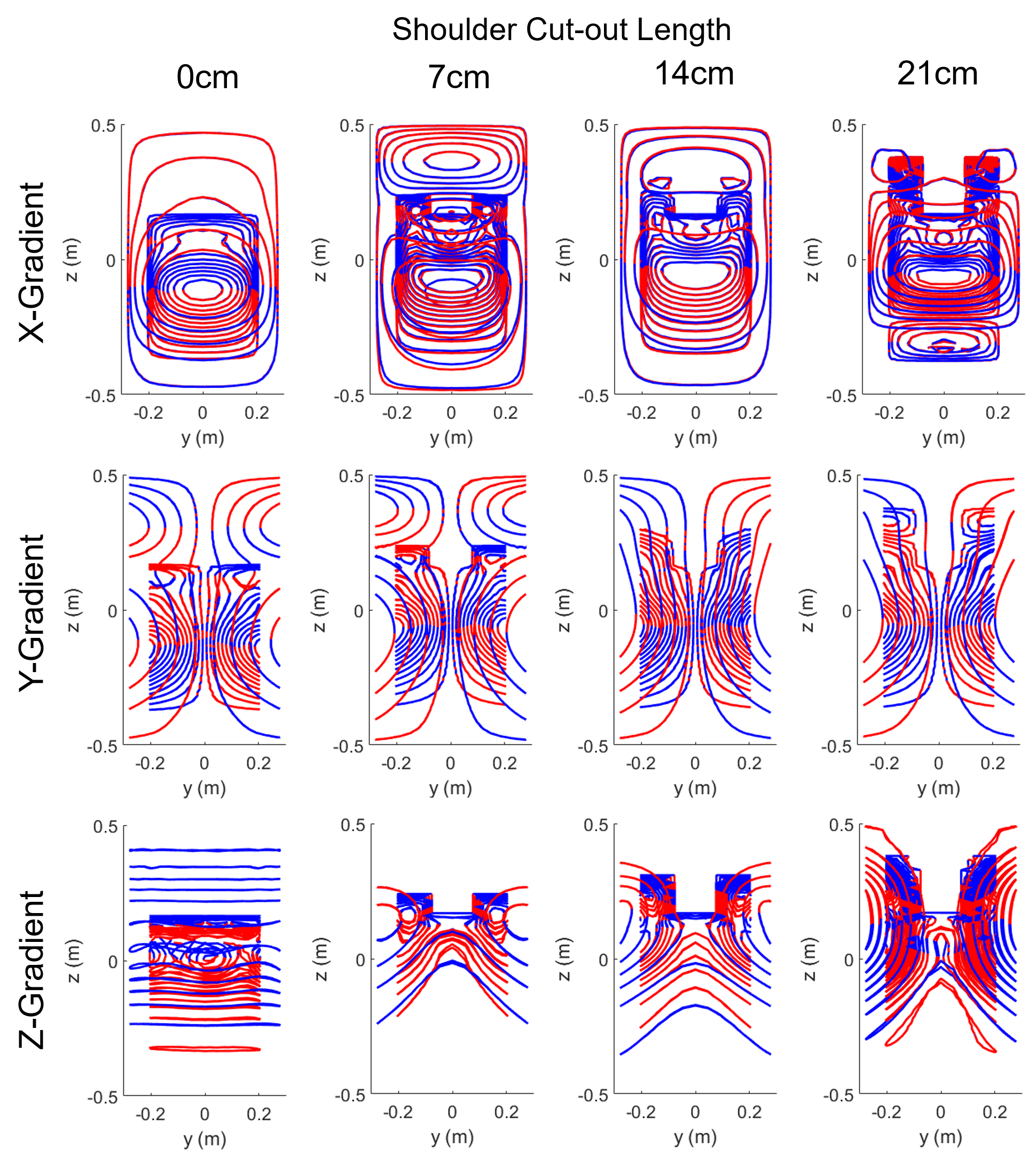
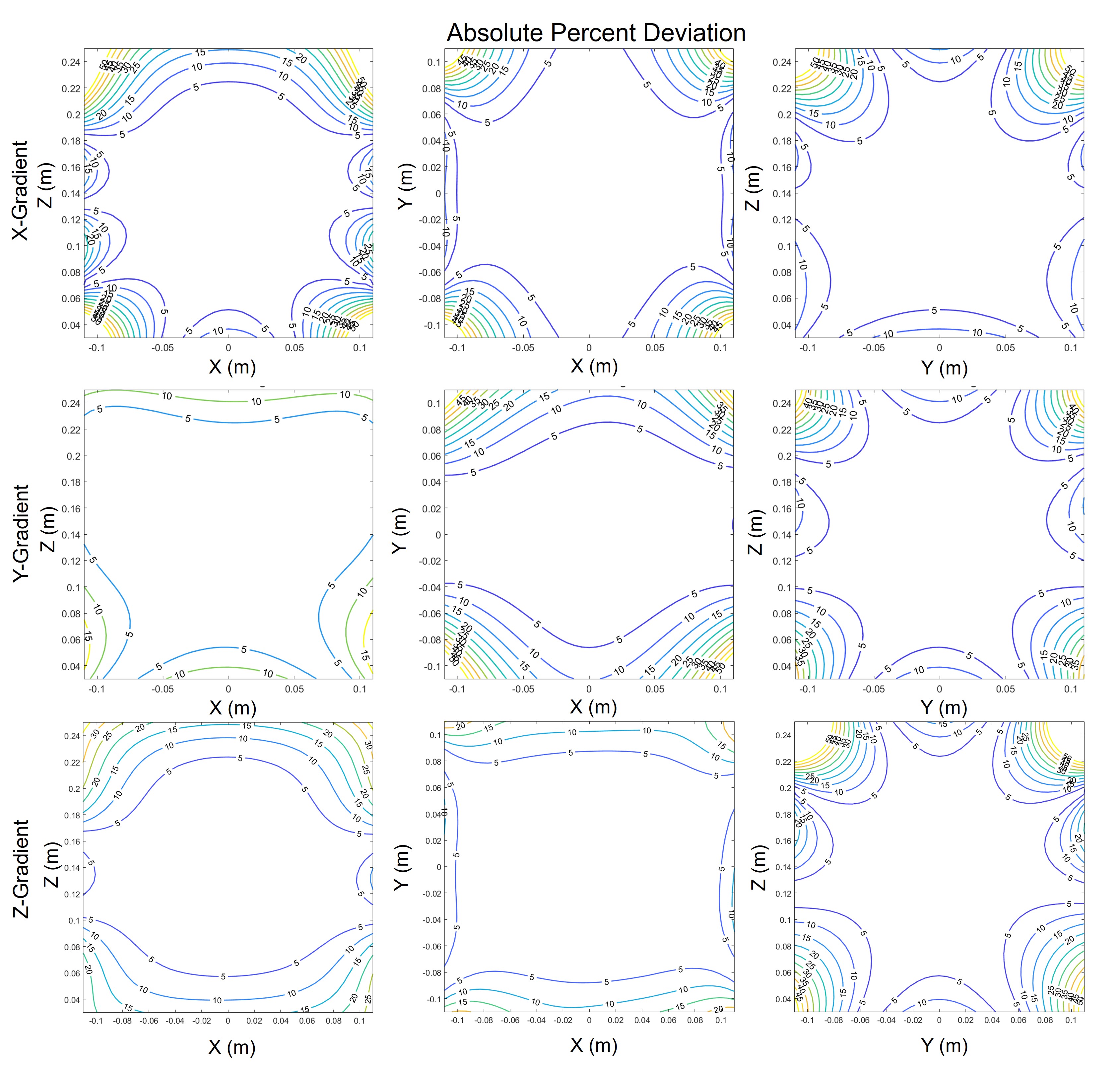
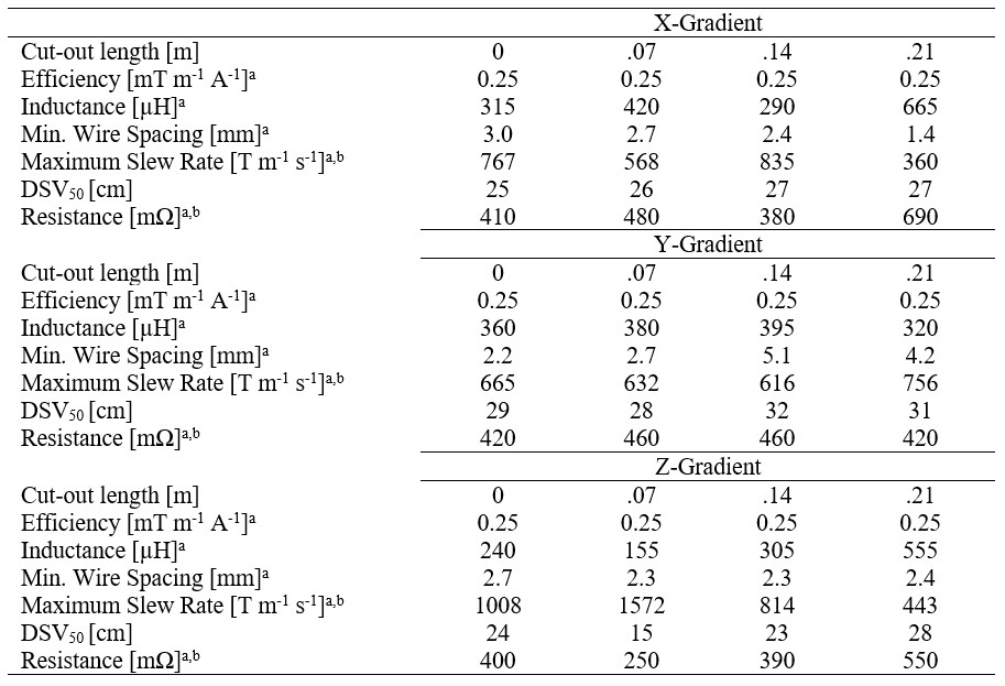
Table 1: Theoretical Electromagnetic and Electrical Properties of Example Shoulder Cut-out X-, Y-, and Z-Gradient Coils in Figure 1
aValues scaled to an efficiency of 0.25 mT/m/A
bValues calculated based on a gradient amplifier capable of driving 330A at 1200V.