1475
Design of a shimming coil matched to the human brain anatomy1Dept. of Radiology · Medical Physics, Medical Center University of Freiburg, Faculty of Medicine, University of Freiburg, Freiburg, Germany, 2Max Planck Institute for Biological Cybernetics, Tuebingen, Germany, 3Department of Biomedical Magnetic Resonance, University of Tuebingen, Tuebingen, Germany
Synopsis
We propose a novel design method of a shim coil specially optimized for the human brain. Numerical results demonstrate the validity of the method. The resulting coil layouts can pave a way towards a novel shimming coil specifically intended for human brain shimming. The proposed design method can be extended to other applications and organs.
Introduction
The recent years have seen significant progress in improved shimming for the human brain using higher-order spherical harmonics (SH) coils$$$^1$$$ and multi-coils$$$^{2-7}$$$. Although all these coils outperform the routine second order spherical harmonic shimming, coil elements of these coils were not designed with an explicit consideration of the magnetic field maps observed in the target organ. Here we propose a design method for shim coils based on the singular vector decomposition and the stream function method$$$^{8}$$$ using human-brain field maps. To find an optimal number of coil elements of the array a cross validation technique is applied. The numerical results demonstrate the validity of the design method.Methods
Whole brain $$$\mathbf{B}_0$$$ field maps of twelve subjects in seven head orientations each were acquired. Phase unwrapping and first order shimming (realizable by linear gradients) were applied in post-processing. Each of the resulting field maps was used as a target magnetic field. A stream function on a cylindrical surface of 360 mm diameter and 300 mm length was then optimized to minimize the standard deviation of the residual magnetic field over the whole brain. During the optimization, the coil power dissipation was constrained to obtain a wire pattern of a shim coil with the same residuals as for SH shimming with a certain predefined order (referred to as a target order). Finally, stream functions on the surface were obtained for each of the field maps to form a matrix with 84 columns.
The singular-value decomposition (SVD) was performed on this matrix and the resulting left-singular vectors (referred to as components), corresponding to several largest singular values, were used to obtain wire patterns of coil elements. A performance analysis for a different number of components was then obtained for each brain field map. The standard deviation of the residual magnetic field was minimized and compared to the residual of SH shimming with a given order. The highest SH order inferior to the designed coil is referred to as achieved order while the channel acount corresponds to the minimum number of components to achieve a certain SH shimming capability.
To test the generalization ability of the designed coil, the leave-one-out cross-validation technique9 was used: out of 12 subjects, eleven subjects were assigned to the training group and one was assigned to the validation group. The procedure was repeated 12 times such that each subject was sequentially assigned to the validation group. Field maps in the training group were used to design a shim coil using SVD, which was then applied to the validation group.
Results and discussions
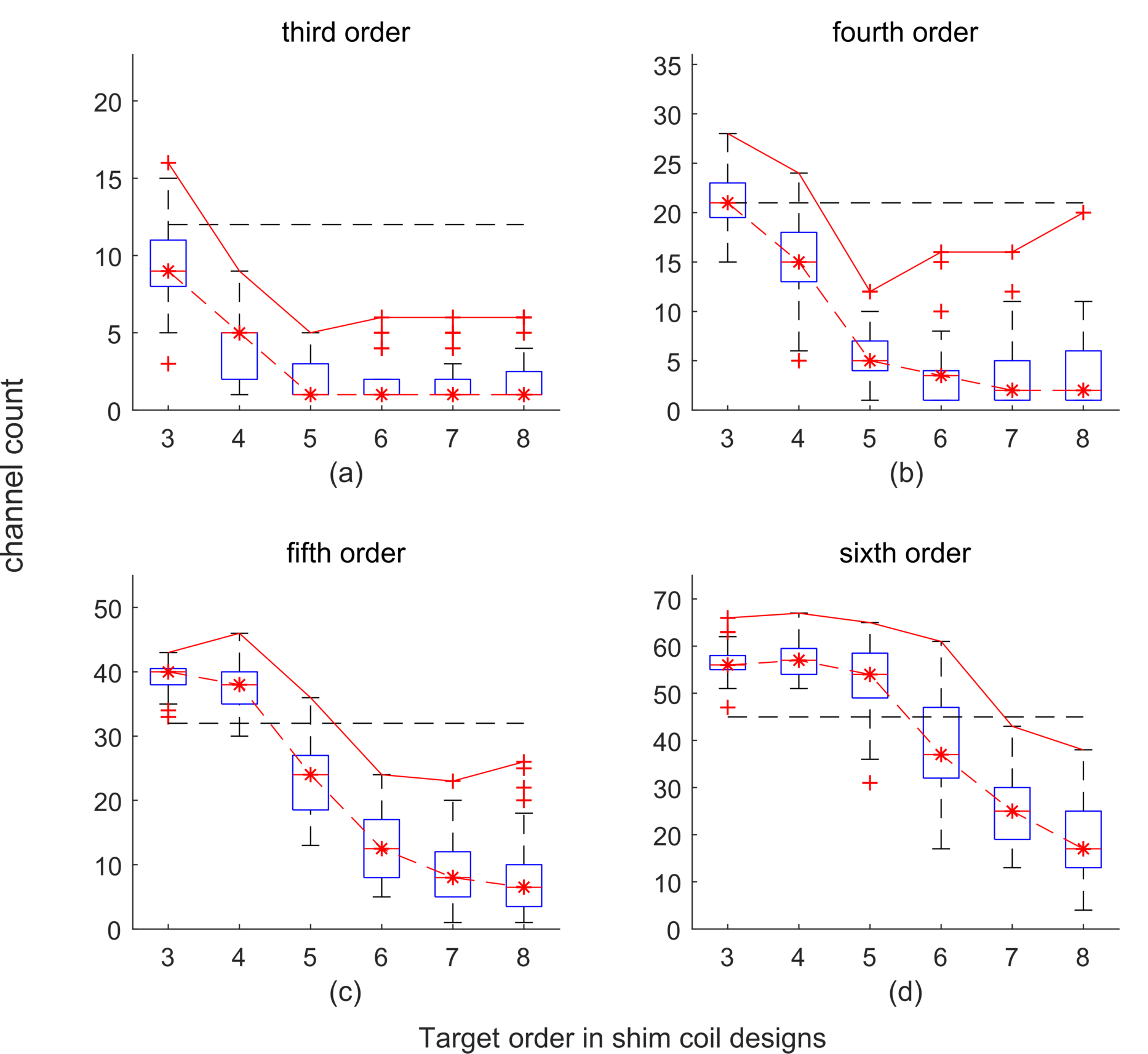
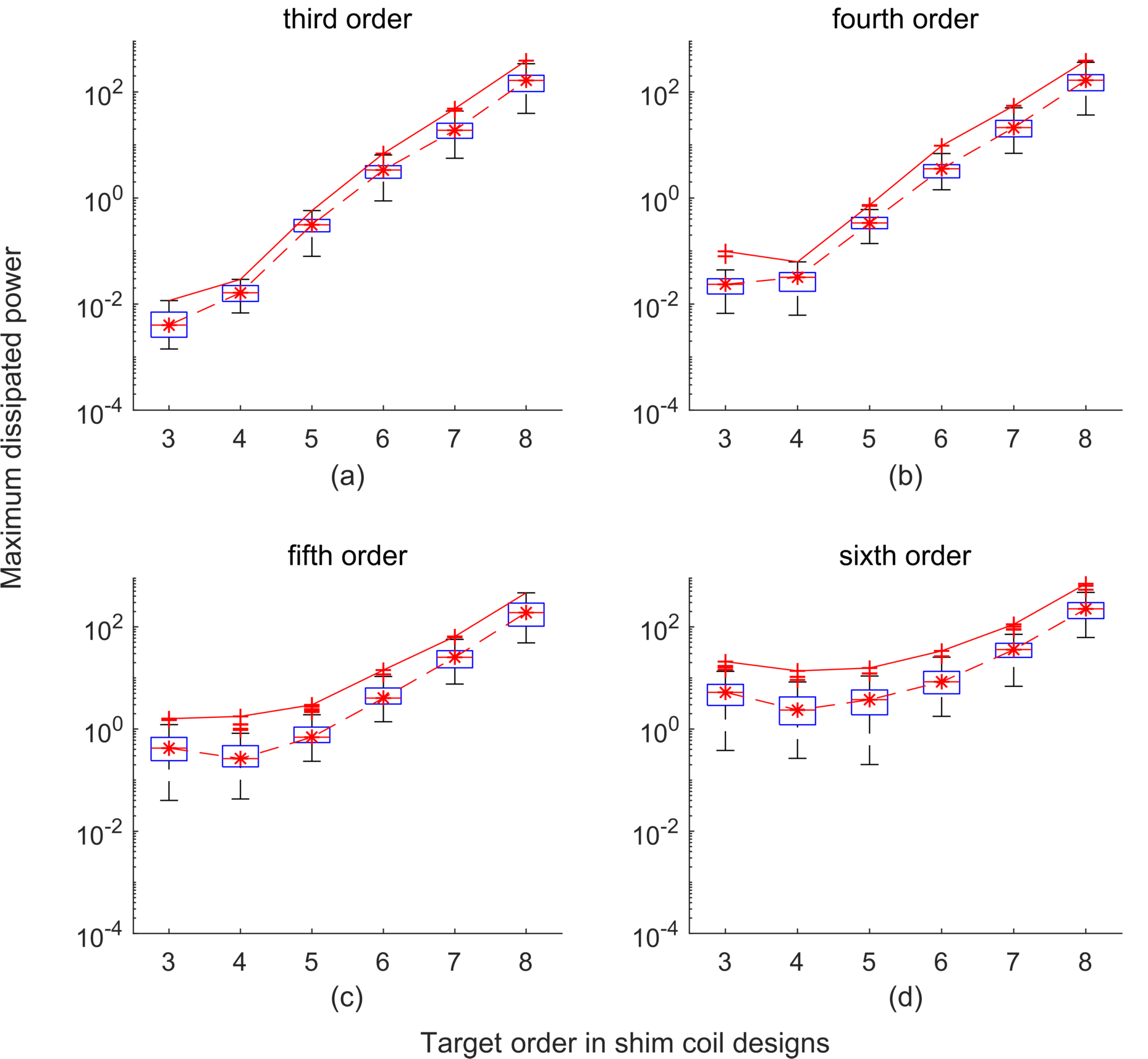
Figure 1 and 2 show the box plots of the channel counts and maximum dissipated power for the field maps across all validation groups. As seen in Figure 1, the median value of the channel count decreases with the increase of a target order. Moreover, when the target order is equal to, or greater than the achieved order, the median value of the channel count tends to be lower than the total numbers of SH functions. Although the selection of the higher target order can lead to an increase of the maximum dissipated power, as shown in Figure 2, it can be acceptable from an engineering perspective based on previously realized air-cooled coils.
Figure 1b-f show that in some cases the maximum channel count tends to vary in a U-shape with increased target order. In those cases the values at the transition points can be selected as the numbers of coil elements of the designed coil. Examplarily, 12 and 24 can be selected as the total number of coil elements to obtain SH shimming capability of the fourth and fifth order, respectively, for the field maps in the validation groups. Here the target orders are equal to 5 and 6, respectively. Compared with the corresponding SH functions, the total numbers of needed shim channels are reduced to 57 % and 77 %, respectively.
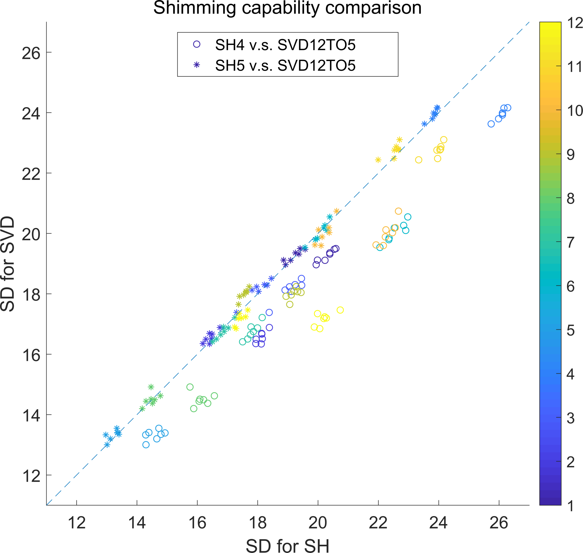
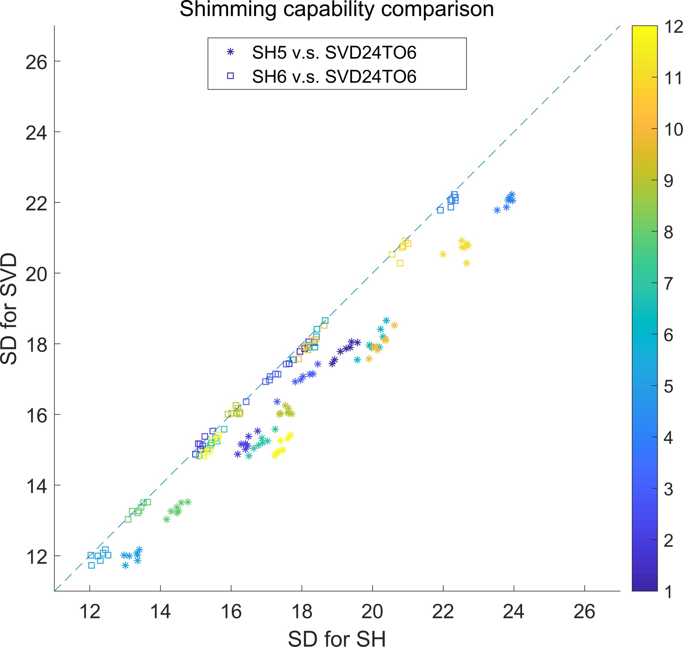
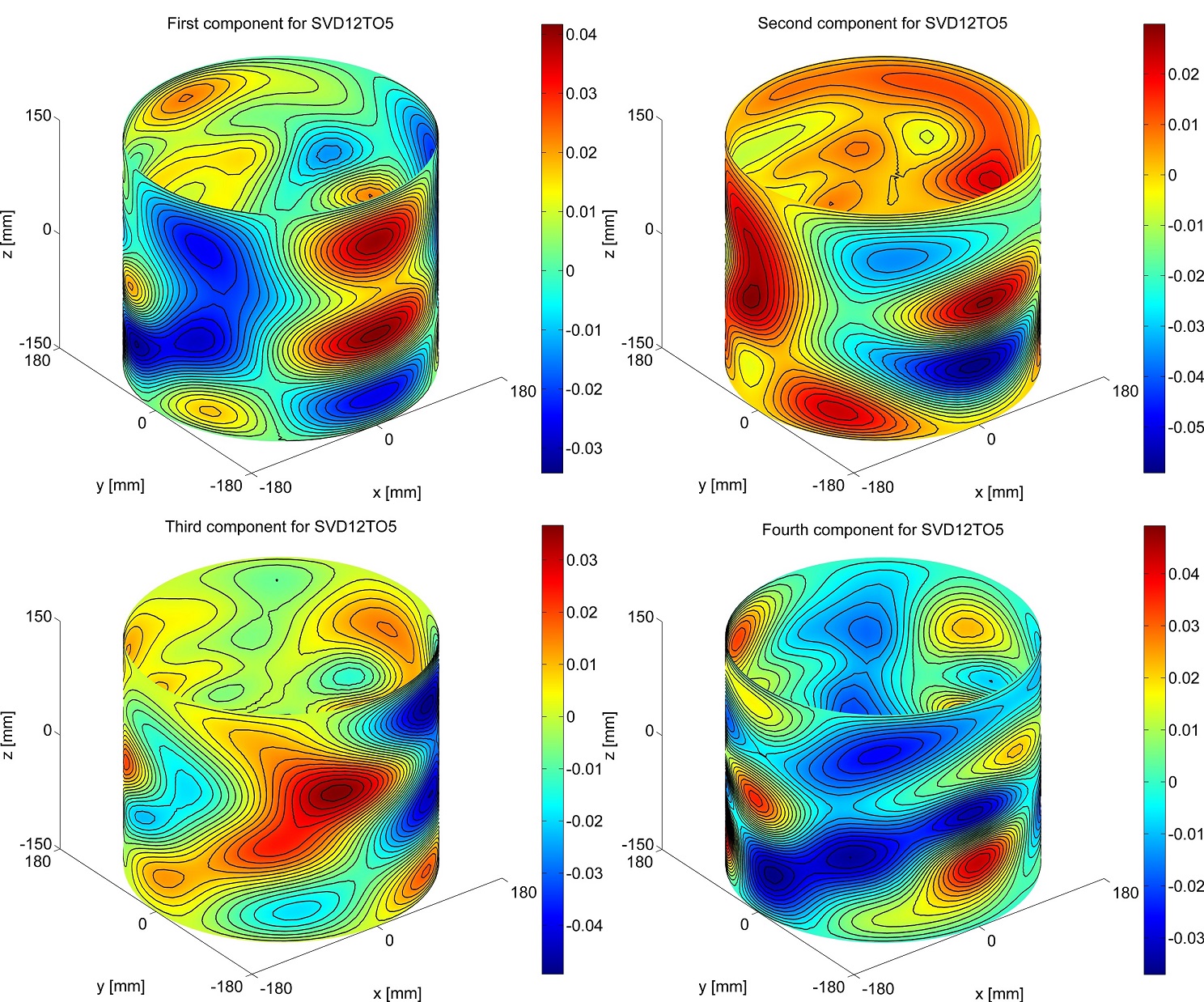
Figure 3 and 4 show scatter plots of standard deviations for all field maps of all subjects using 12 and 24 SVD components compared to higher order SH shimming. Using more than 39 and 90 percent of all the field maps these components lead to equal or better shimming capability of the fifth and sixth order SH shimming, respectively. Figure 5 depicts the first four wire patterns of the 12 components which are very different from conventional SH coil layouts10.
Acknowledgements
This work was supported by the German Research Foundation (DFG) (Grant Numbers. ZA 422/5-1, ZA 422/6-1 and KS 658/13-1) and the European Research Council Proof-of-Concept Grant ‘mrSANE’ grant agreement 755466.References
1. Pan et al. Role of very high order and degree B0 shimming for spectroscopic imaging of the human brain at 7 Tesla. Magn Reson Med. 2012;68: 1007-1017.
2. Juchem et al. Magnetic field modeling with a set of individual localized coils. J Magn Reson. 2010;204:281-289.
3. Stockmann et al. A 32-Channel Combined RF and B0 Shim Array for 3T Brain Imaging. Magn Reson Med. 2016;75: 441-451.
4. Han et al. Integrated Parallel Reception, Excitation, and Shimming (iPRES). Magn Reson Med. 2013;70:241-247.
5. Truong et al. Integrated RF/shim coil array for parallel reception and localized B0 shimming in the human brain. NeuroImage. 2014;103:235-240.
6. Jia et al. Using a matrix gradient coil for shimming of the human brain. In: Proc. ESMRMB 2016, s77-s78.
7. Aghaeifar et al. Dynamic B0 shimming of the human brain at 9.4 T with a 16-channel multi-coil shim setup, MRM early view. doi:doi.org/10.1002/mrm.27110.
8. Peeren GN. stream function approach for determining optimal surface currents. J Comput Phys. 2003;191:305-321.
9. Devijver et al. Pattern Recognition: A Statistical Approach. 1982. London, GB: Prentice-Hall.
10. Hudson et al. Finite‐length shim coil design using a fourier series minimum inductance and minimum power algorithm, Concepts Magn Reson Part B Magn Reson Eng. 2010;37B:245-253.
Figures