1470
A cryogen-free actively shielded HTS magnet for a 1.5 T MRI system1Neoscan Solutions GmbH, Magdeburg, Germany, 2Institute for Medical Engineering, Otto-von-Guericke University, Magdeburg, Saxony-Anhalt, Germany, Magdeburg, Germany
Synopsis
A cryogen free actively shielded magnet for 1.5 T MRI is being developed. High temperature superconductor is used for the fabrication of the magnet. We bring this first prototype for neonatal MRI system which requires more compact dimension and tighter stray field of the magnet. Magnet design has been finished and one coil of the total seven coils has been built and tested. The experimental results are satisfactory in terms of cooling performance, joint resistance and magnetic field. It successfully approves the feasibility of the concept and more results will be shown when the conference starts.
INTRODUCTION
A conventional 1.5 T MRI scanner for adult MRI has some disadvantages for neonatal imaging: its long bore in adult size limits the visual and physical access to the neonates; its broad stray field, large dimension and large weight bring challenging requirements to the siting in e.g. the NICU; the helium usage requires a special ventilation system and extra cost for a quench event, the successive refilling of the cryogen or an emergency stop event.METHODS
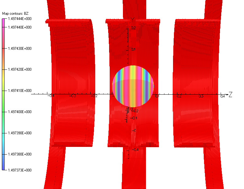
Owing to the high temperature margin, a high temperature superconducting (HTS) magnet can be a competitive option for a cryogen-free magnet 1 2 3 4 5 6. In this research, we are developing an HTS magnet prototype for neonatal and thus smaller / more compact MRI system with complete absence of any helium difficulties. The magnet is designed in consideration of the following issues: field homogeneity, stray field range, wire consumption, size of the magnet and the convenience of fabrication 7 8. It has a room temperature bore of about 0.5 m in diameter and 1 m in length. It is actively shielded. The HTS magnetic field is excited by four main coils and is actively shielded by three shielding coils, which are symmetrically situated in the magnet. It generates 1.5 T magnetic field in an 18 cm DSV (diameter of spherical volume) with peak to peak field homogeneity less than 50 ppm (fig 1). The stray field is within a 2 m (axial direction) x 1.5 m (radial direction) boundary, which is about a half size for an adult MRI in the two directions. The sensitivity of the field homogeneity in terms of fabrication tolerances and screening current in the superconductor has been studied. It indicates that most of the impure components in the DSV are low order spherical harmonic items and can be annulled easily by gradient coils and passive shimming. Each HTS coil is fabricated in a way of stacking double pancakes. Each double pancake is wound with commercial Bi2223 HTS wire (Sumitomo Electric Industries, Ltd). The HTS joints are made by means of pressured soldering for a very low joint resistance. A highly stable power supply is used to maintain the field stability for the magnet with about 100 nano-Ohm resistance. The cooling system is built in the way of cryogen-free and light-weight. A GM cryocooler and copper cooling bus system are used to cool down the magnet. Strengthened cooling for each double pancake is applied by cooper disc insert so that the Ohmic heat of the joint can be removed effectively.RESULTS
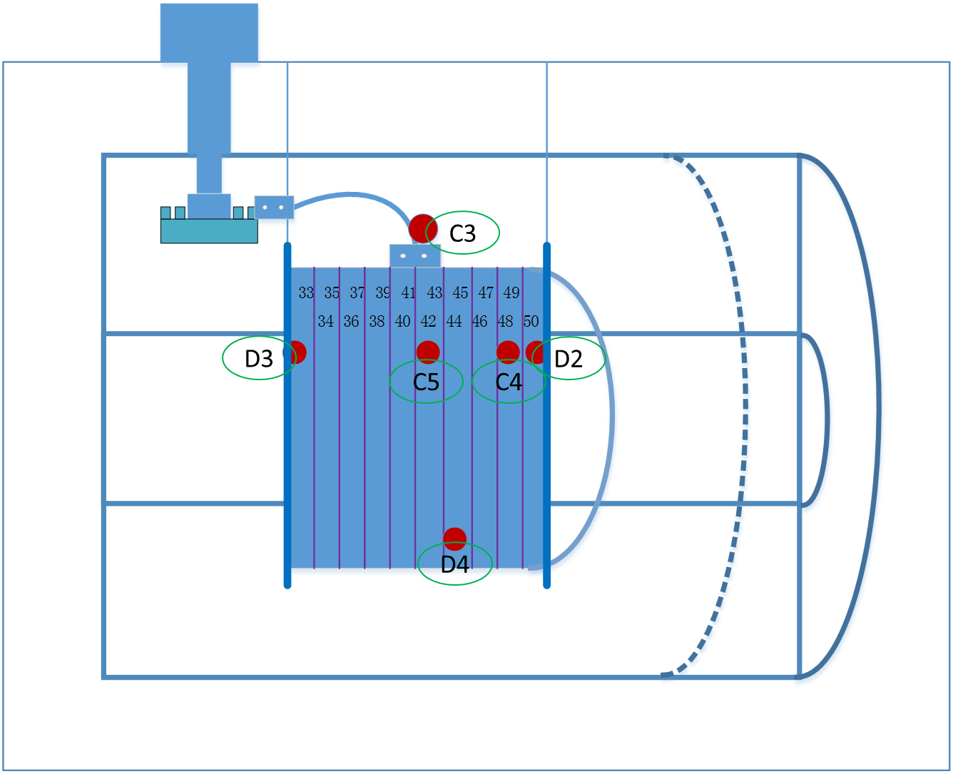
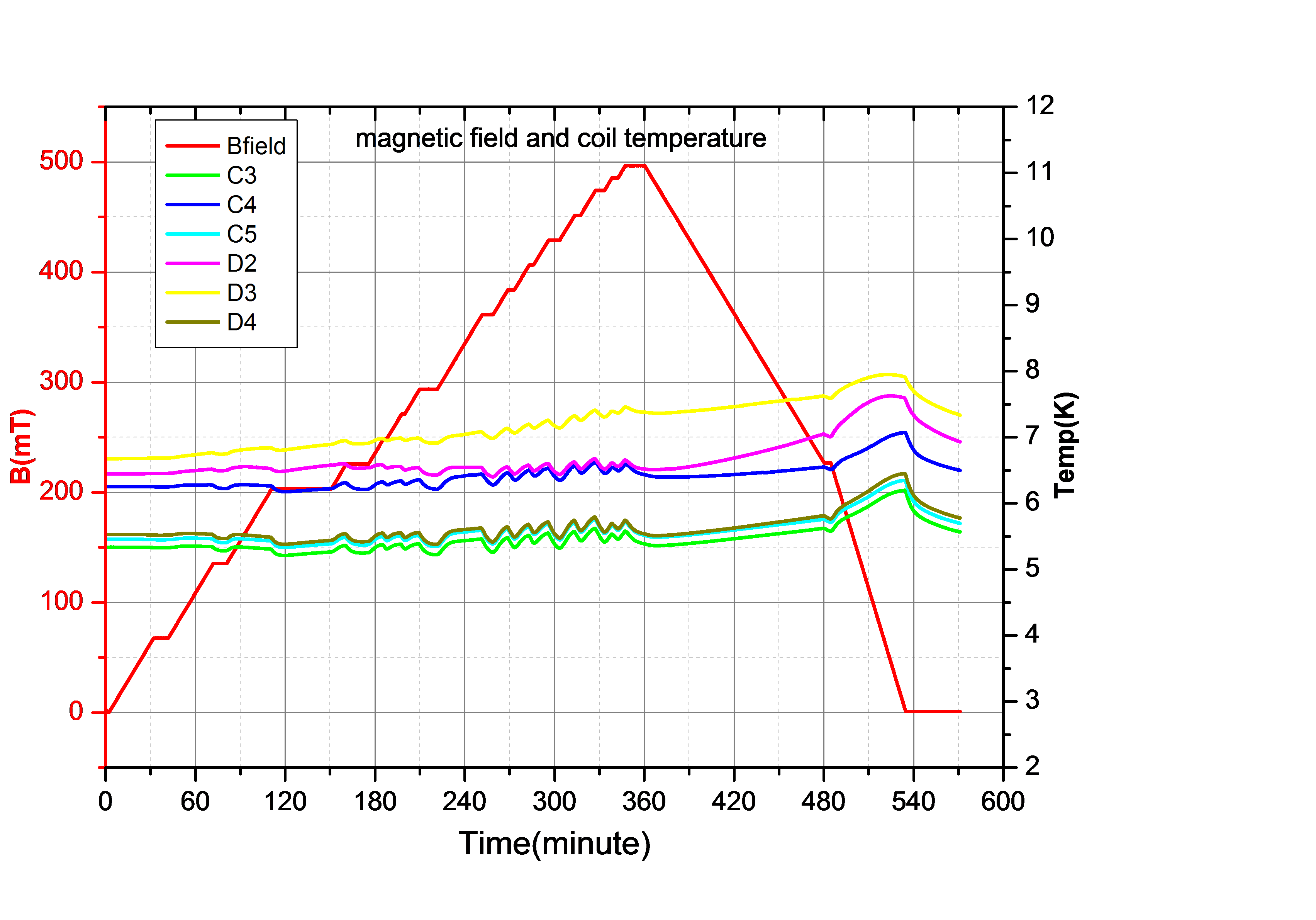
Before the abstract was done, all of the design of the magnet system had been finished. One of the seven coils had been fabricated and brought to a solitary test for cooling down and full current charging. The temperatures at the cryogenic system and the HTS coil were measured (fig 2). Voltage drops at the joints after current charging were recorded. Magnetic field at the coil center is obtained by a Hall sensor.DISCUSSION
The results we had when the abstract was done show that the cryogenic system had a good performance for the HTS magnet; the temperature of the coil reaches 6K (fig 3), close to the level of the conventional LTS magnet using liquid helium; the field strength of the coil is 496 mT as expected by calculation (fig 3); joint resistance is 2~3 nano Ohm, among the top levels referred from other literature 9 10 11 12. We expect the whole magnet will be finished at the end of the year 2018 and more results will be shown when the conference starts.CONCLUSION
Simulations and current test data of running a magnet coil at certain temperature level below 10K demonstrate the feasibility of this magnet concept.Acknowledgements
This work is performed at the Research Campus STIMULATE and is partly funded by the European Regional Development Fund (ref. ZS /2017/06/86528).References
1. Michael Parizh, Yuri Lvovsky and Michael Sumption. Conductors for commercial MRI magnets beyond NbTi: requirements and challenges. Supercond. Sci. Technol. 30 (2017) 014007 (16pp).
2. Ben Parkinson. Design considerations and experimental results for MRI systems using HTS magnets. Supercond. Sci. Technol. 30 (2017) 014009 (16pp).
3. B. J. Parkinson, K. Bouloukakis and R. A. Slade. A compact 3T all HTS cryogen-free MRI system. Supercond. Sci. Technol. 30 (2017) 125009 (12pp).
4. Kwang Lok Kim, Jung-Bin Song, Yoon Hyuck Choi, Dong Gyu Yang, and Haigun Lee. Feasibility Study of a No-Insulation 1.5-T/600-mm All-REBCO Magnet for MRI Systems. IEEE Transactions on Applied Superconductivity, vol. 27, no. 4, June 2017 4600204.
5. Juan Bascu˜n´an, Philip Michael, Seungyong Hahn, Thibault Lecrevisse, and Yukikazu Iwasa. Construction and Test Results of Coil 2 of a Three-Coil 800-MHz REBCO Insert for the 1.3-GHz High-Resolution NMR Magnet. IEEE Transactions on Applied Superconductivity, vol. 27, no. 4, June 2017 4300504.
6. H. Miyazaki, S. Iwai, M. Takahashi, T. Tosaka, K. Tasaki, S. Hanai, S. Ioka, K. Watanabe, S. Awaji, and H. Oguro. Design of a REBCO Insert Coil for a Cryogen-Free 25-T Superconducting Magnet. IEEE Transactions on Applied Superconductivity, vol. 25, no. 3, June 2015 4603205.
7. N. Amemiya and K. Akachi, Magnetic field generated by shielding current in high Tc superconducting coils for NMR magnets. Supercond. Sci. Technol., vol. 21, no. 9, Jun. 2008, Art. no. 095001.
8. Y. Li, L. Wang and Q. Wang. Electromagnetic Design of HTS Insert for Ultrahigh Field NMR Magnet. IEEE Transactions on Applied Superconductivity, vol. 28, no. 3, pp. 1-5, April 2018, Art no. 4602105.
9. Soumen Kar, Rajesh Kumar. Development of Joints Between Two Parallel SS-Laminated BSCCO/Ag HTS Tapes. IEEE Transactions on Applied Superconductivity, vol. 20, no. 1, Feb. 2010.
10. Y. Kim, J. Bascuñán, T. Lecrevisse, S. Hahn, J. Voccio, D. Park, and Y. Iwasa. YBCO and Bi2223 coils for high field LTS/HTS NMR magnets: HTS-HTS joint resistivity. IEEE Trans. Appl. Supercond., vol. 23, no. 3, p. 6800704, Jun. 2013.
11. Zou Chunlong, Son Yuntao, Huang Xiongyi, Liu Chenglian, Shahab Ud-Din Khan, Xi Weibin, Lu Kun. Experimental investigations on the soldering performances of the joints for Bi-2223/Ag tapes. Physica C 508 (2015) 17–20.
12. Goro OSABE, Kohei YAMAZAKI. Ni Alloy Laminated High Strength Bi-2223 Wire. SEI TECHNICAL REVIEW, No. 84, April 2017
Figures