1469
Single H-Bridge Shimming Driver1Department of Radiology, Medical Physics, Medical Center University of Freiburg, Faculty of Medicine, University of Freiburg, Freiburg, Germany
Synopsis
The multi-channel shimming coils have been proposed to improve the magnetic field homogeneity locally. The one-coil-one-driver solution is preferred to keep the high flexibility. The linear-mode and switch-mode solutions are feasible for such low current applications. However, the switch-mode current driver has the advantage of smaller size in space-limited situations, such as for coils with high number elements. Here we present the design and implementation of a single H-bridge shimming driver. The performance comparison of analog controller and digital controller is shown, and also two different pulse width modulation methods.
Introduction
The matrix coils, multi-coils or local shim coil arrays has been developed for B0 shimming recently 1-3. Due to the low-current requirement and the high complexity and low flexibility of dynamically controlled switch-based method 4,5, the conventional approach that one-coil-one-amplifier is preferred for shimming applications. The first open-source shimming amplifier was introduced recently, capable of 8A/12V with low cost 6. However, because of the natural bulky dimensions of linear-mode design, its application might be limited to coils with a low number element. The in-bore switch-mode class-D shimming amplifier has been proposed to address the power loss of long cables and potential RF interference, capable of 9A/10V with small size 7. Here we present design and implementation of a prototype single H-bridge shimming driver. The performance of analog controller and digital controller is compared and discussed.Methods
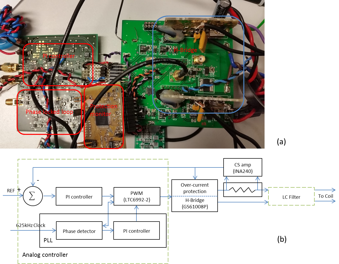
Amplifier stage: The amplifier is an H-bridge which control pulse is provided by an external controller (either analog controller or digital controller). GS61008P (100V eGaN transistor, GaN Systems) is used to achieve high efficiency at 625 kHz. Each bridge output is fed through a fourth-order LC low-pass filter. The DC power supply voltage is set to 24V to achieve high slew rate as needed for dynamic shimming. The output current is monitored with a current sense resistor (5mΩ, CSM3637, Vishay) and zero-drift current-sense amplifier (INA240A1, Texas Instruments).
Protection: An RMS-to-DC converter (AD8436, Analog Devices) and comparator (ADCMP601, Analog Devices), and an absolute value circuit and comparator, that provides the RMS and peak over-current protection, respectively. Additionally current of DC power supply is monitored with 1mΩ current sense resistor and current sense amplifier, which provides another stage of over-current protection. A Complex Programmable Logic Device (CPLD, 5M80ZT100C5, Intel/Altera) is used to monitor and aggregate the individual fault signals.
Analog controller: An analog operational amplifier-based Proportional-Integral (PI) controller provides modulation signal based on the error signal to a commercial pulse width modulator (LTC6992-2, Linear Technology/Analog Devices). Then the control pulses are generated for amplifier module. The frequency of pulse width modulator is set to 625 kHz. Phase lock loop (PLL) including a phase detector and a PI controller was designed to synchronize multi-channel amplifiers with external reference clock and compensate for the frequency error of pulse width modulator. Figure 1 shows a photograph and block diagram of the driver with the analog controller.
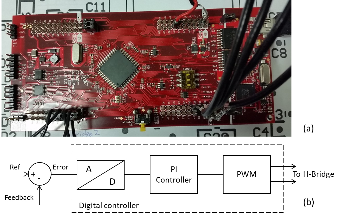
Digital controller: As an alternative solution, TMS320F28377S LaunchPad development kit (LAUNCHXL-F28377S, Texas Instruments) is used to implement the digital PI controller and PWM modulator. The integrated analog-to-digital converter (ADC) was configured to 12-bit resolution and 50 MHz sampling frequency. The resolution of digital PWM modulator is larger than 12-bit at 625 kHz carrier frequency, because of the micro-edge-positioning step size of integrated high-resolution PWM modulator is between 150 and 310 picoseconds, which avoid the limit cycling (steady state oscillation). Figure 2 shows a photograph and a block diagram of the digital controller.
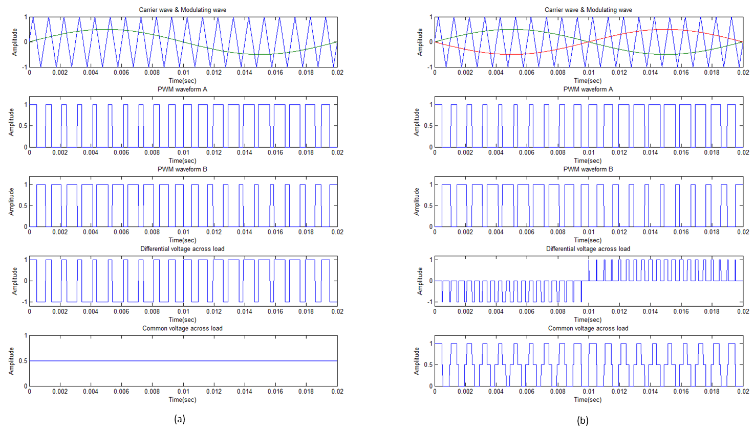
Modulation method: The conventional pulse width modulation (Binary AD modulation) and new pulse width modulation (Ternary BD modulation, which has been widely used for decade for audio amplifiers 8) were implemented. Figure 3 presents details of the two PWM methods.
Results and Discussion
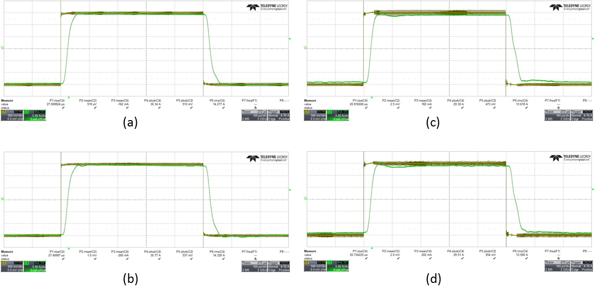
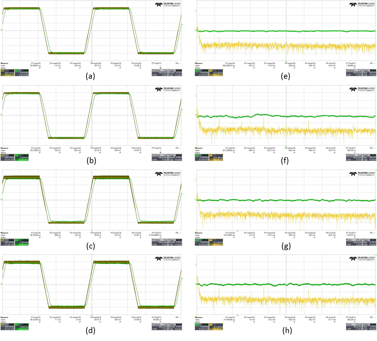
The circuit was tested with a home-built matrix coil element (12µH, 0.01Ω) in benchtop. Figure 4 shows the output waveform when the circuit is driven by a step function to test the transient response. Figure 5 shows the trapezoid current waveform with two different controllers and two different modulation methods.
The jitter of PWM output of the analog controller is about 25 nanoseconds because of the usage of PLL, which slightly increases the low frequency noise of the ripple current. Whether this ripple current increase will have an effect on shimming performance still needs to be investigated.
Compared to the analog controller, low frequency noise of ripple current is slightly increased when the digital controller is used. The high frequency harmonics have appeared in new modulation, and low frequency noise is slightly increased. The advantage of new modulation that relieve the filter design is only observed when fully differential filter is used (the results are not shown). However, the effect of the common-mode voltage on the mutual coupling within the coil array and with gradient coils must be taken into account.
The analog controller is preferred for the low current shimming applications due to the ease of construction. The question whether the new modulation may be advantage for shimming is still under investigation. To further improve the performance of digital controller, a feed-forward module needs to be implemented.
Acknowledgements
This work is supported by the European Research Council Proof-of-Concept Grant ‘mrSANE’ grant agreement 755466.References
1. Juchem C, Rudrapatna S U, Nixon T W, de Graaf R A. Dynamic multi-coil technique (DYNAMITE) shimming for echo-planar imaging of the human brain at 7 Tesla. NeuroImage 105: 462-472 (2015).
2. Stockmann J P, Witzel T, Keil B, et al. A 32-channel combined RF and B 0 shim array for 3T brain imaging. Magn Reson Med 75: 441-451 (2016).
3. Littin S, Jia F, Layton K, et al. Development and implementation of an 84-channel matrix gradient coil. Magn Reson Med 79: 1181-1191 (2018).
4. Harris C T, Handler W B, Chronik B A. A new approach to shimming: the dynamically controlled adaptive current network. Magn Reson Med 71: 859-869 (2014).
5. Yu H, Layton K L, Littin S, et al. A multi-channel gradient driver system for matrix gradient coil s. Proc. ISMRM24, 3548 (2016).
6. Arango N, Stockmann J P, Witzel T, et al. Open-source, low-cost, flexible, current feedback-controlled driver circuit for local B0 shim coils and other applications. Proc. ISMRM24, 1157 (2016).
7. Twieg M, Griswold M A. In-bore high efficiency current driver. Proc. ISMRM25, 2708 (2017).
8. Muggler P, Chen W, Jones C, et al. A filter free class D audio amplifier with 86% power efficiency. ISCAS (2004).
Figures