1467
An Irregular Aubert Ring-Pair-Aggregate Optimized with Improved Gradient for Head Imaging in a Low-field Portable MRI System1Singapore University of Technology and Design, Singapore, Singapore
Synopsis
We present a design and optimization of an irregular Aubert ring-pair-aggregate permanent magnet array that generates 2D B0-field with an improved gradient for head imaging for a low-field portable MRI system. The ring-aggregates are discretized into fan-shaped sections with identical angles and varying outer diameters for design and optimization. Genetic algorithm (GA) was used. Compared to a Halbach-array, the proposed array shows an increased in field strength (111.2 mT) with a controlled inhomogeneity, and an enhanced gradient (off-center-concentric-pattern). It leads to better reconstructed images using simulations where the central blurring area is eliminated.
INTRODUCTION
Recently, a Halbach-array was used to supply both B0-field and built-in gradient fields in the transverse direction for head imaging in an MRI system. With this, an MRI system can be miniaturized and gradient coils are omitted, paving a way towards portability [1-2]. However, the field pattern is quadrupolar and non-bijective, thus the array has to be rotated for imaging. Moreover, the central area of the reconstructed images is blurred due to the lack of gradient. To solve this problem, the effort has been made to obtain a B0-field with a linear gradient to favor imaging [3]. Here, we propose an irregular Aubert ring-pair-aggregate permanent magnet array, on top of the previously proposed Aubert ring-pair-aggregate [4]. Compared to a Halbach-array, it provides an increased magnetic field strength, an enhanced gradient (off-center-concentric-pattern), and a controlled inhomogeneity along the longitudinal direction. It effectively improves the quality of the reconstructed images.METHODS
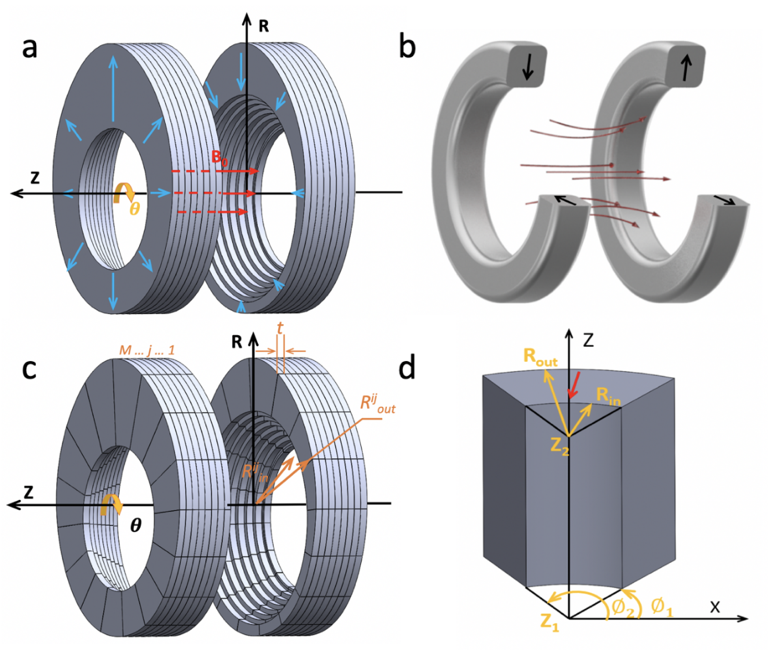
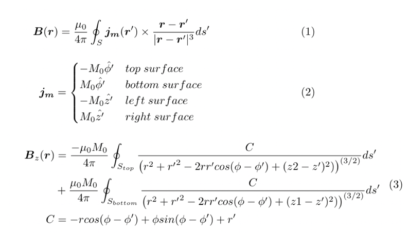
The proposed design (Fig.1(a)) is based on an Aubert ring-pair (Fig.1(b)) [5]. The rings on the two sides are identical. On each side, the M rings (thickness of $$$t$$$ each) form an aggregate [4]. The $$$j_{th}$$$ ring on one side is discretized into N fan-shaped sections (Fig.1(c)), where the $$$i^{th}$$$ section (Fig.1(d)) has an inner radius of $$$R_{in}^{ij}$$$ and an outer one of $$$R_{out}^{ij}$$$. The distance between the two innermost edges of the rings was fixed to be 200 mm. For the $$$j_{th}$$$ ring, the inner radius for each segment was set to be the same as $$$R_{in}^{ij}$$$. The outer radii of the $$$i_{th}$$$ segments for all the rings are set to be the same as $$$R_{out}^{ij}$$$. All the $$$R_{in}^{ij}$$$ and $$$R_{out}^{ij}$$$ ($$$i= 1, ..., N$$$, and $$$j =1, …, M$$$) were optimized to generate a B0-field with a field strength of larger than 100 mT, a field homogeneity<10000 ppm, with gradients. The field of view (FOV) is a circular area with a diameter of 200 mm in the central transversal plane of the array. The optimization tool is a Genetic algorithm (GA). To accelerate the optimization, a current model for a fan-shaped ring segment (Fig.1(d)) was derived and implemented for a fast forward calculation. The equations for the current model are shown in Fig. 2.RESULTS
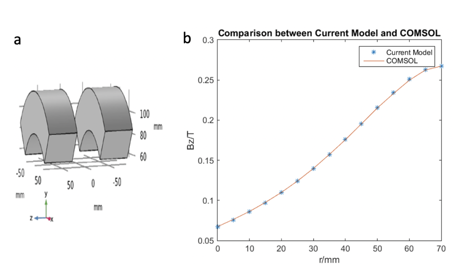
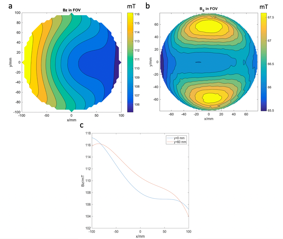
To validate the derivation, the fan-shaped segment pair (Fig.3(a)) was calculated using both Eq.(3) and COMSOL Multiphysics. Fig. 3(b) shows both results along the radial direction and they agree with each other well. Symmetry is applied here to increase the optimization efficiency. The optimization results in an Aubert ring-pair-aggregate with an irregular width of the ring (Fig.1(a)). Fig.4(a) shows the resultant field pattern of the optimization, showing an off-center-concentric-pattern. The average field strength is 111.2 mT and the field homogeneity is 99970 ppm in the FOV. Fig.4(c) shows field plot along the x-direction at different values of y. It shows a linear gradient at y=60 mm. Slight distortions are observed when y approaches y = 0 mm.
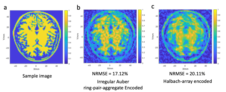
B0-field in Fig.4(a) and that of a Halbach-array (Fig.4(b)) were used for encoding for imaging for a phantom in Fig.5(a) (rotation angle = 36, sample points = 128, noise level = -60 dB). Fig.5 shows the reconstructed images based on simulations. As shown, the reconstructed images encoded by the proposed magnet array shows a normalized root mean square error (NRMSE) of 17.12%, which is a reduction by 15% of that by a Halbach-array (20.11%). Comparing both, the central blurring of an image by a Halbach-array is greatly reduced when the proposed magnet array is used for encoding.
CONCLUSION & DISCUSSION
We present a design and optimization of an Aubert ring-pair-aggregate permanent magnet array with irregular widths of the rings. It generates relatively high field strength (111.2 mT) with an enhanced gradient (off-center-concentric-pattern) and a controlled inhomogeneity (99970 ppm), which favors head imaging in a low-field portable MRI system. A current model was developed for the forward calculation, and GA was used for the optimization. It was successfully shown that the proposed array helps to reduce the blurry areas in a reconstructed image when its B0-field was used for encoding for imaging.Acknowledgements
Zhi Hua Ren would like to thank the support of the Singapore University of Technology and Design President Fellowship.
References
- Cooley CZ, Stockmann JP, Armstrong BD, Sarracanie M, Lev MH, Rosen MS, Wald LL. Two‐dimensional imaging in a lightweight portable MRI scanner without gradient coils. Magnetic resonance in medicine. 2015 Feb;73(2):872-83.
- Ren ZH, Obruchkov S, Lu DW, Dykstra R, Huang SY. A low-field portable magnetic resonance imaging system for head imaging. InProgress in Electromagnetics Research Symposium-Fall (PIERS-FALL), 2017 2017 Nov 19 (pp. 3042-3044). IEEE.
- Cooley CZ, Haskell MW, Cauley SF, Sappo C, Lapierre CD, Ha CG, Stockmann JP, Wald LL. Design of Sparse Halbach Magnet Arrays for Portable MRI Using a Genetic Algorithm. IEEE transactions on magnetics. 2018 Jan;54(1):1-2.
- Z. H. Ren, W. C. Mu, and S.Y.Huang, “Design and Optimization of a Ring-Pair Permanent Magnet Array for Head Imaging in a Low-field Portable MRI System”, IEEE Transactions on Magnetics, 2018, in press
- Aubert, G., Centre National de la Recherche Scientifique CNRS, 1991. Cylindrical permanent magnet with longitudinal induced field. U.S. Patent 5,014,032.
- Ren ZH, Maréchal L, Luo W, Su J, Huang SY. Magnet array for a portable magnetic resonance imaging system. InRF and Wireless Technologies for Biomedical and Healthcare Applications (IMWS-BIO), 2015 IEEE MTT-S 2015 International Microwave Workshop Series on 2015 Sep 21 (pp. 92-95). IEEE.
Figures