1465
Low-cost gradients using commercially-available printed circuit boards1Institute of Applied Physics, Tsukuba, Japan, 2MRTechnology Inc., Tsukuba, Japan
Synopsis
Gradient coils often need expensive, manufacturing processes such as gluing, etching, and/or milling. The purpose of this study is to propose low-cost gradients using commercially-available printed circuit boards (PCBs). For proof of concept, we fabricated four types of PCB-gradients for different MRI systems: cylindrical transverse gradients for a 1.5 T, 280 mm-bore superconducting magnet (SCM), for a 4.7 T, 89 mm-bore SCM, and for a 9.4 T, 54 mm-bore SCM, and planar gradients for a 0.2 T, 160 mm-gap permanent magnet. We verified that the PCB gradients outperform the hand-wound gradients.
INTRODUCTION
Gradient coils are often constructed using solid or hollow copper winding wires, or using cuts in a continuous copper surface. Gradient coils needs to satisfy different requirements such as the high mechanical stiffness, the high-voltage isolation between the different layers, and a sufficient thermal conductivity, and thus they often need expensive, manufacturing processes such as gluing, etching, and/or milling. Here we propose low-cost gradients using commercially-available printed circuit boards (PCBs). We fabricated four types of PCB-gradients for different MRI systems, and evaluated the performance of the PCB gradients.METHODS
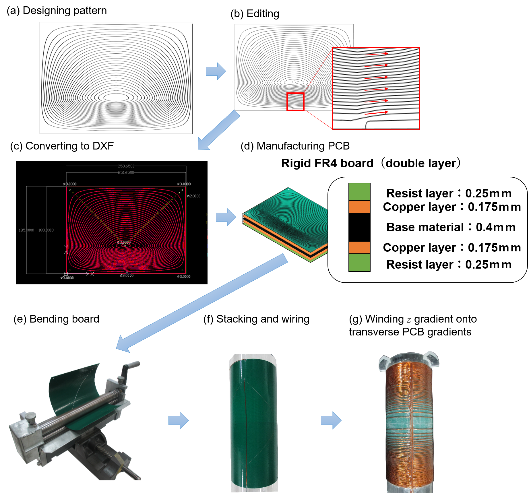
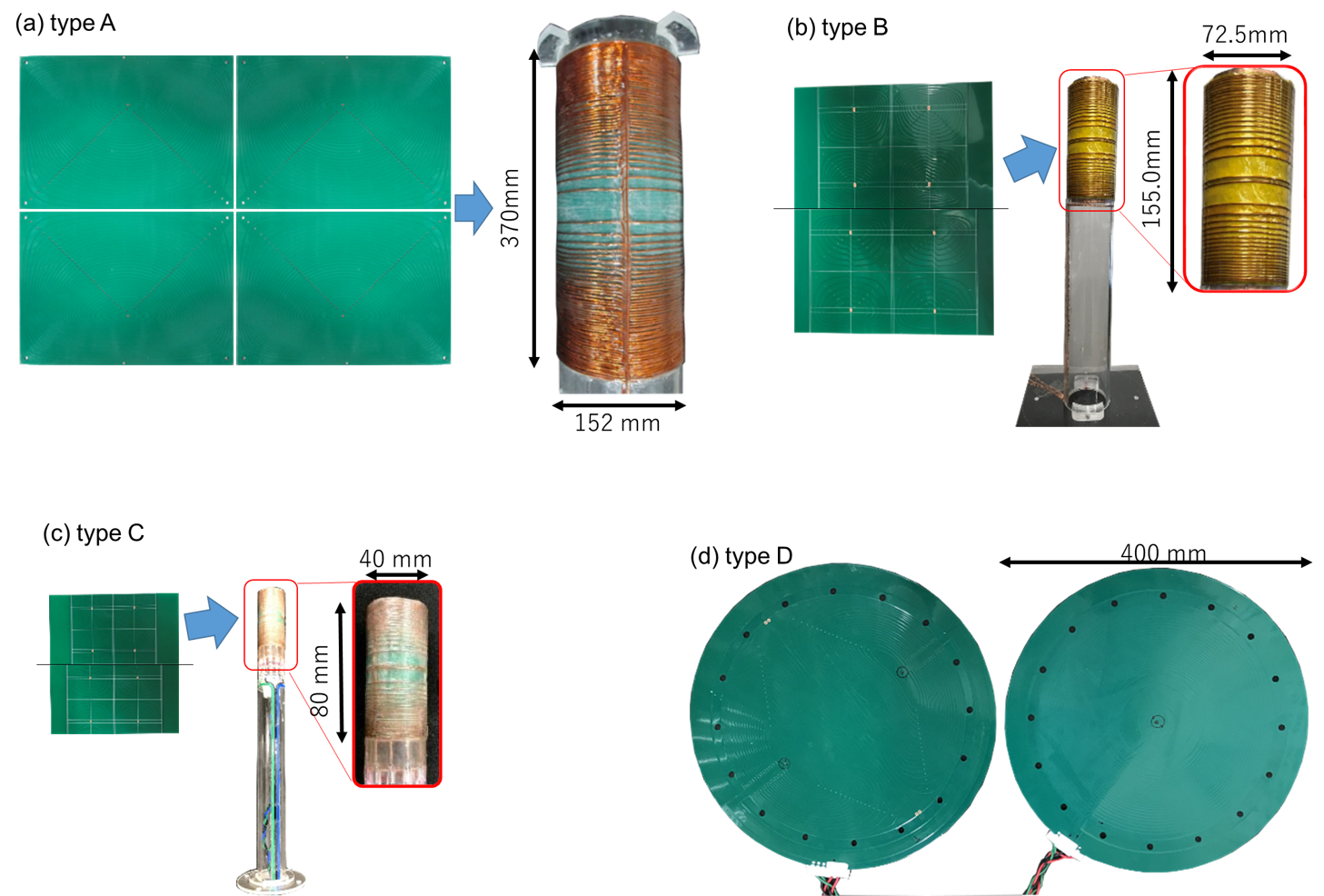
We fabricated four type of PCB-gradients: cylindrical transverse gradients for a 1.5 T, 280 mm-bore SCM (type A), for a 4.7 T, 89 mm-bore SCM (type B), and for a 9.4 T, 54 mm-bore SCM (type C), and planar gradients for a 0.2 T, 160 mm-gap permanent magnet (type D). We edited coil winding patterns, converted them to a drawing exchange format (DXF), and passed an order to an e-commerce company (p-ban.com [1]). The company fabricated flat-type PCBs according to the DXF data. The specification of the PCBs was listed in Fig. 1. The production costs were $2k (type A; x and y), $1.5k (type B; x and y), $10k (type C; x and y), and $40k (type D; x, y, and z).
Fabrication of cylindrical gradients (A, B, and C): The fabrication process of the type A gradient was shown in Fig. 2. The supplied PCBs were bent manually using a bending machine, and stacked together. The type A gradient had a large diameter, so the bent PCBs were fixed onto an acrylic pipe to ensure the high stiffness. After wiring, each PCB gradient was firmly fixed using an epoxy resin. The z gradient coils were fabricated by winding wires by hand onto the transverse PCB gradients.
Fabrication of planar gradients (D): x, y, and z PCB gradients were stacked, wired, and fixed firmly using an epoxy resin.
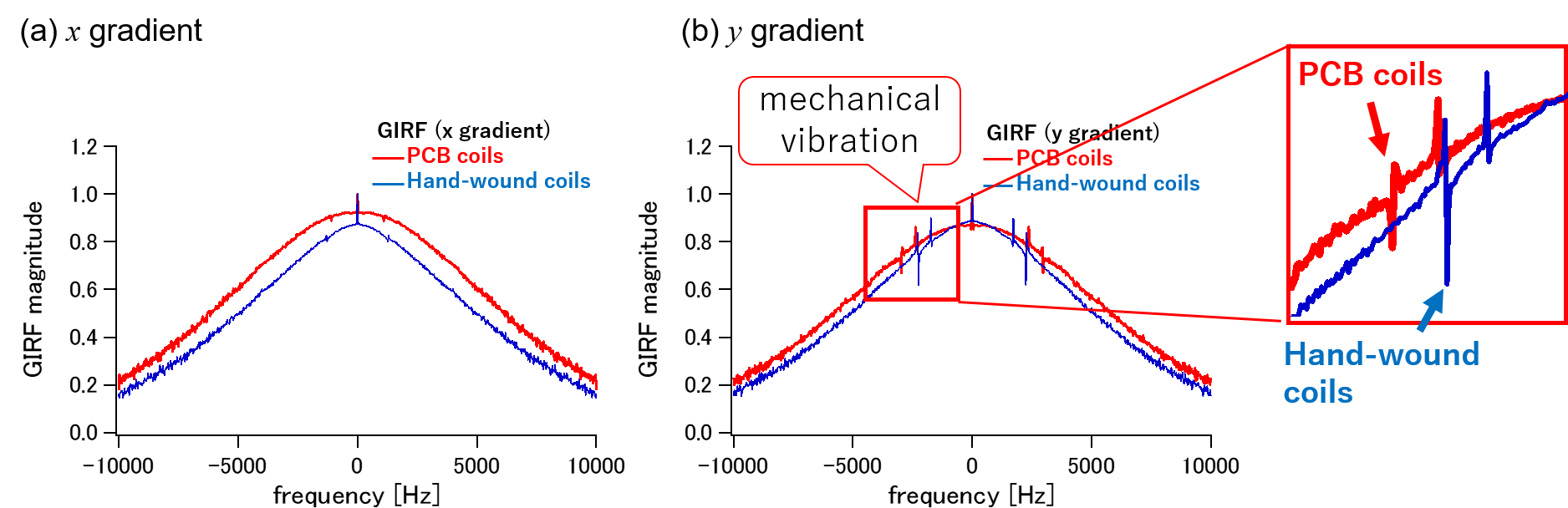
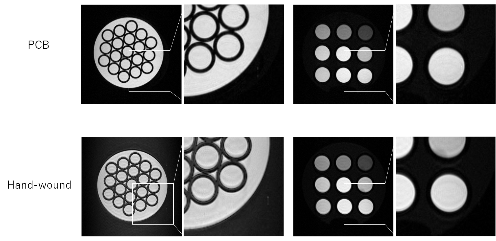
The performance of the type-A, PCB gradients was compared with that of a hand-wound gradient with the same winding pattern. Gradient impulse response functions (GIRFs) of the two gradients were measured using a field-camera system [2]. The image quality test was performed using a fast spin echo sequence (echo train length = 4, FOV = 64 mm x 64 mm, slice thickness = 10 mm; echo spacing = 40 ms, TE/TR = 40/2000 ms, matrix size = 256 x 256, bandwidth = 50 kHz; sequential ordering).
RESULTS AND DISCUSSION
Figure 3 shows the photos of the PCB gradients. All the gradients fulfilled the designed specifications. Figure 4 compares the GIRFs of the type-A, PCB and hand-wound gradients. The PCB gradients had the wider bandwidth than the hand-wound ones, possibly because the smaller manufacturing error of the PCB gradients may lead to the reduced eddy-current field arising from the asymmetry of the gradient field. The PCB gradients had also reduced peaks attributed to the mechanical oscillation, indicating the higher mechanical stability than the hand-wound coils. The FSE image acquired with the PCB gradients (Fig. 5(a)) showed high image quality with less ghosting artifacts, compared with the FSE image acquired with the hand-wound gradients (Fig. 5(b)). These results indicate the better gradient fidelity of the PCB gradients.
With this proof-of-concept study, we fabricated only transverse gradients for the cylindrical geometry. The longitudinal, cylindrical gradients using PCB boards have more electrical wire joints, and care needs to be taken to ensure high reliability of the electrical contacts.
CONCLUSION
We fabricated the four-type PCB gradients for different MRI systems and verified the high performance of the PCB gradients.Acknowledgements
No acknowledgement found.References
[1] http://www.en.p-ban.com/
[2] Y. Kobayashi, K. Kose, and Y. Terada, “Development of a field camera system for a customized 1.5 T compact MRI system,” Proc. Intl. Soc. Mag. Reson. Med. 26, 4426, (2018)
Figures