1464
A short gradient coil with “outer-wall direct cooling" for human brain imaging1Neuroimaging Research Branch, National Institute on Drug ABuse, NIH, Baltimore, MD, United States, 2Mechanical Engineering, University of Maryland, College Park, MD, United States
Synopsis
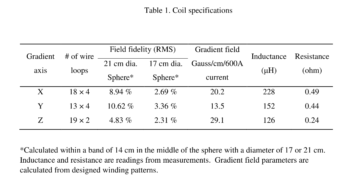
Optimal gradient performance is arguably a pre-requisite to realize the full potential of ultrahigh field MRI. The values of using tailored gradient coils for brain imaging have been well acknowledged. Unfortunately, conventional head-only gradient coils have two major technical limitations, i.e. limited shoulder clearance and limited cooling capacity. A new design, coined “auto-rim” gradient coil, combined with a novel cooling method, named “outer-wall direct cooling”, is proposed to fundamentally solve these two technical problems. As a proof-of-concept, we have built a protype gradient coil capable of generating 20.2, 13.5 and 29.1 Gauss/cm/600 ampere current along X, Y and Z, respectively.
Introduction
The values of using tailored gradient coils for brain imaging have been well acknowledged1-4. Unfortunately, conventional head-only gradient coils have two major technical limitations, i.e. limited shoulder clearance and limited cooling capacity. Several approaches have been proposed to address these two problems5-7. This work demonstrates alternative approaches to these two problems.Methods
Shoulder clearance: in conventional cylindrical coil design, the coil has to reach certain length in order to achieve a volume with high fidelity to the linear gradient field suitable for human brain imaging. Because the inner diameter of the cylindrical coil does not clear the shoulders of a typical adult, one cannot place the center of the human brain to the center of the gradient coil (see Fig. 1A for illustration). Anatomically, the outlines of neck and shoulder have an angle of about 115 degrees (Fig. 1A). One can take advantage of this feature and design a slanted surface that is parallel to the shoulder outline and place the return paths on the slanted surface (see Fig. 1B). The return paths are no longer a limiting factor that prevents the brain from reaching the “sweet spot” of the coil. The X and Y gradients have similar wiring patterns but shifted by 90 degrees. The coil looks like an “auto rim” when viewed from either end (Fig. 1C).
Cooling: Modern gradient coils are typically cooled by forced convection with the coolant inside the current-carrying element (e.g. copper tube). This method is limited by the copper tube diameter: a large inner diameter is preferred for heat dissipation; a compact configuration of cooling using small diameter tubing is preferred for enhancing current density (thus higher gradient coil efficiency).
We propose a cooling method, named “out-wall direct cooling” (Fig. 2): we use solid electrical conductors (e.g. copper wires), and design cooling channels in direct contact with the electrical conductors. Solid copper wires are also beneficial in reducing overall electrical resistance. Since coolant is in direct contact with the outer wall of the electrical conductors, it minimizes thermal resistance between coolant and copper tubing. Importantly, heat transfer area is determined by the size and the number of cooling channels, which is no longer limited by the inner diameter of a copper tube. Coolant channel inlet and outlet are designed to minimize pressure drop of the coolant flow. This approach simultaneously achieves: i) low thermal resistance between coolant and copper wires; 2) controllable large heat transfer area; 3) extreme low pressure drop; and 4) compact current carrying element for high gradient field strength.
Results
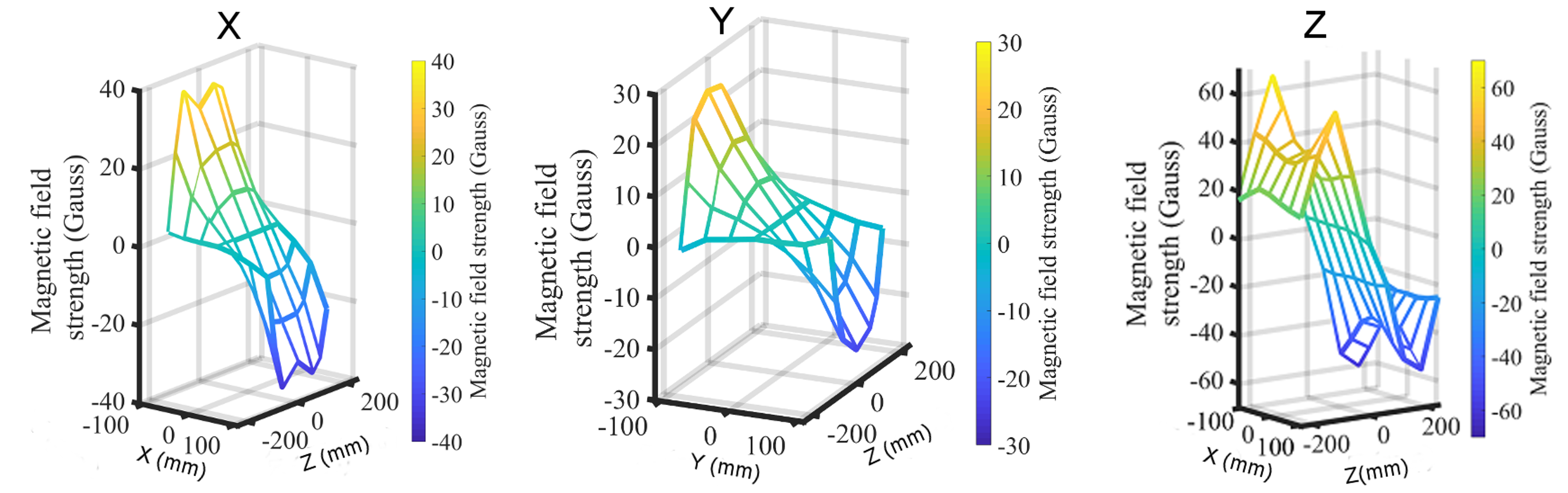
Moment-weighted conjugate gradient descent8 was applied to design a three-axis torque-balanced gradient coil. The inner-most layer was Z with a conventional cylindrical shape, followed by X and Y, which have cylindrical shape in the middle and slanted surfaces at both ends. The length of Z cylinder is 28 cm, which is the effective length of the coil. The inner diameter of Z is 30 cm, similar to the one developed by Wong et al.2. The outer most diameter in the slanted surface is 46.5 cm. This diameter was chosen to ensure enough clearance so that the coil could be placed on the patient tables of the commercial MRI scanners, and could be conveniently moved into/out of the magnet without the need for additional mounting structure. The angle between the cylindrical surface and the slanted surface is 115o. We applied 3D printing techniques to build major frames for X and Y gradients with designed shape, winding patterns and cooling channels. Z gradient was constructed with G10 fiberglass using 4 axis CNC machine. Solid copper wires (Gauge 12) were embedded into individual X, Y and Z gradients. The three gradients were potted together with high thermal conductivity and high dielectric epoxy. Figure 3 shows the prototype coil. Table 1 lists coil specifications. Field mapping is illustrated in Fig. 4.
Discussion
If one applies the same approach to design a head-only MRI system, i.e. there is no body gradient coil, and assumes the outer diameter to be 70 cm --- the standard inner diameter of commercial MRI magnets, the inner diameter of the gradient can be much enlarged (e.g. 45 cm), allowing for coil arrays necessary for parallel imaging9. The slanted surface can be extended to 14 cm or more, allowing for more return current loops to be placed on this plane, and thus further shortening the overall length of the coil. The larger diameter would provide more space for the design of active shielding of eddy current as well.Acknowledgements
This work was partially supported by NIDA Intramural Research Program, NIH (Dr. H. Lu), and by NSF (CBET1336778, Dr. B. Yang)
References
1. Bandettini, P.A., Wong, E.C., Hinks, R.S., Tikofsky, R.S. & Hyde, J.S. Time course EPI of human brain function during task activation. Magn Reson Med 25, 390-397 (1992).
2. Wong, E.C., Jesmanowicz, A. & Hyde, J.S. Echo-planar imaging of the human brain using a three axis local gradient coil. in Society of Magnetic Resonance in Medicine 105 (Berlin, 1992).
3. Turner, R., et al. Echo-planar imaging of intravoxel incoherent motion. Radiology 177, 407-414 (1990).
4. Kwong, K., et al. Dynamic magnetic resonance imaging of human brain activity during primary sensory stimulation. Proc Natl Acad Sci U S A 89, 5675-5679 (1992).
5. Wade, T.P., Alejski, A.B., Janos Tsarapkina, Dina Hinks, R. Scott McKinnon, & Graeme C Rutt, B.K.M., Charles A. Design, construction and initial evaluation of a folded insertable head gradient coil. 4851 (Proc. Intl. Soc. Mag. Reson. Med., 2014).
6. Amm, B.C., Aksel, B. & Wangerin, K.A. Transversely folded gradient coil. (US patent, US7932722B2).
7. Mathieu, J.-B., Lee, S.-K.G., Dominic Lin, Jian Budesheim, Eric Piel, Joseph E, hiagarajan, N.H., Christopher J. Schenck, John F. Tan, Ek Tsoon Fiveland,, Eric Park, K.H., Yihe Bernstein, Matt A. Huston III, John Shu, Yunhong & Foo, T.K.-F. Development of a dedicated asymmetric head-only gradient coil for high-performance brain imaging with a high PNS threshold. 1019 (Proc. Intl. Soc. Mag. Reson. Med., 2015).
8. Lu, H., Jesmanowicz, A., Li, S.J. & Hyde, J.S. Momentum-weighted conjugate gradient descent algorithm for gradient coil optimization. Magn Reson Med 51, 158-164 (2004).
9. Lee, S.K., et al. Peripheral nerve stimulation characteristics of an asymmetric head-only gradient coil compatible with a high-channel-count receiver array. Magn Reson Med 76, 1939-1950 (2016).
Figures
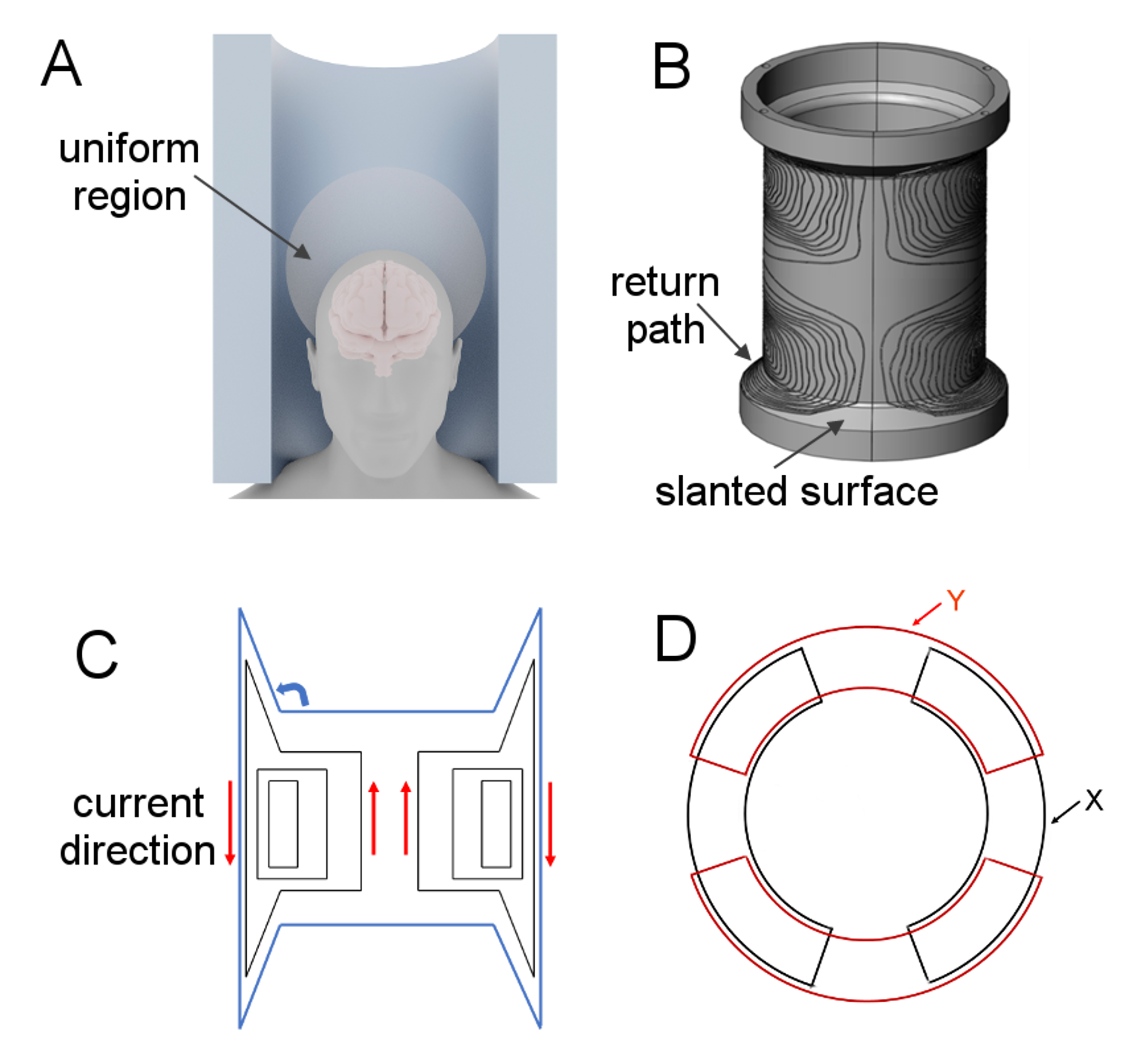
Figure 1. A. Illustration of the so-called “shoulder clearance” problem in conventional head-only gradient coil. The shoulder cannot fit into a typical head-only gradient coil; only part of the uniform region is used for imaging a typical human brain. B and C, proposed coil design. By placing the return paths on the slanted surface parallel to the shoulder, one can shorten the overall length of the coil, and thus minimizing the “shoulder clearance” problem. X and Y gradients have similar winding patterns, but shifted by 90 degrees. The coil looks like an “auto rim” when viewed from either end (D).
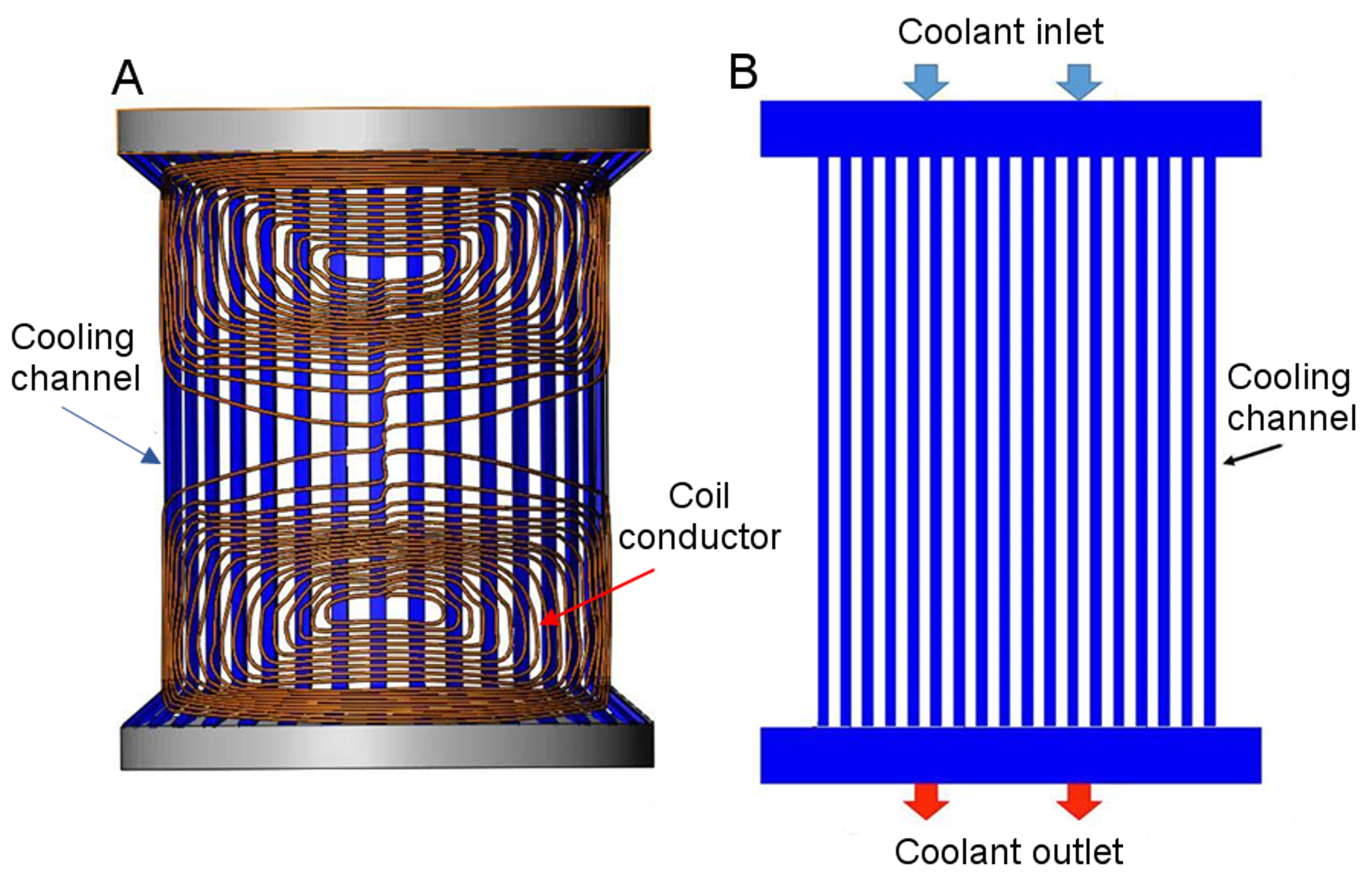
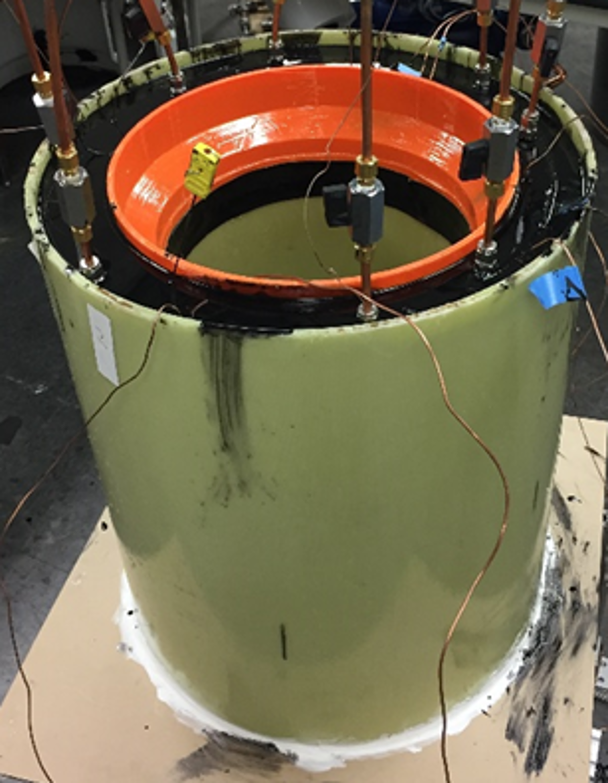
Figure 3. The prototype three-axis gradient coil. Z gradient was built on a fiberglass cylinder (inner most). X and Y were built on 3D-printed frames (invisible here). They were potted together with epoxy along with a large fiberglass cylinder (outer most). The orange frame is a 3D print of an additional slanted surface parallel to that of the X gradient for epoxy potting.