1456
RF-induced heating pattern of a partially immersed conducting implant wire at 7T – its dependence on wire length1Imaging Institute, Cleveland Clinic, Cleveland, OH, United States, 2Radiology, Cleveland Clinic Lerner College of Medicine, Cleveland, OH, United States, 3Physics, Case Western Reserve University, Cleveland, OH, United States
Synopsis
Radiofrequency induced heating at 7T of an insulated wire (exposed at tip) partially immersed in ASTM gel phantom to evaluate safety of scanning partially implanted guidewires, implants like stereo electroencephalography (SEEG) electrodes at different configurations, and conducting wires at that field strength. A transmit-receive coil was used for this study. Heating at certain resonance lengths separated by half a wavelength in air was observed. The heating at resonance lengths were 3-4 times less than that reported earlier at 3T at same specific absorption rate, and under similar configurations and settings.
Introduction
Radiofrequency (RF) induced heating of implants during MRI scans poses a concern for safety. Safety of scanning at 3T with partially implanted guidewires,1, 2 implants like stereo electroencephalography (SEEG) electrodes at different configurations,3, 4 and conducting wires5 have been investigated, from which local maxima of heating at certain resonance lengths of the implanted wires have been identified. With more impetus of clinical studies at higher field like 7T, it becomes pertinent to study similar heating pattern at these field strengths6, 7 and to compare the heating with that at 3T. In this study we have identified the resonance pattern and corresponding temperature changes for scanning partially immersed conducting wire at 7T with head-only transmit-receive coil over a range of wire lengths. The heating behavior was compared with that under identical conditions at 3T.5Methods
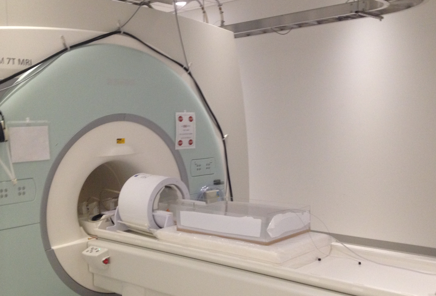
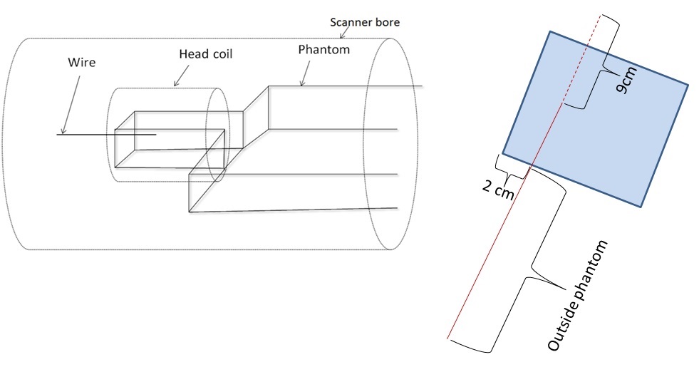
All experiments were conducted in a 7T Magnetom scanner (Siemens, Erlangen, Germany) with a transmit-receive (TxRx) head coil. An ASTM torso phantom was filled up with polyacryclic gel (ASTM F2182-02a) having similar conductivity as human tissue. A 180 cm copper wire (0.7 mm diameter) was entered the phantom along the Z-axis at a position 2 cm inside from the lateral surface of the phantom and with 9cm of its length in the phantom (Fig. 1 and 2). The wire was insulated with 0.45 mm thick polyvinyl chloride (PVC) throughout the length, except for 2mm at the tip (similar to the tip of a real SEEG electrode). Heating of the wire during a turbo spin echo (TSE) scan (TR=10710 ms; TE=52 ms; Flip angle=1200; Turbo factor=15; Echo trains per slice=15) was studied. The specific absorption rate values of the sequence were whole body: 0.2 W/kg, exposed body: 2.7 W/kg, head: 2.7 W/kg. The length of the wire was changed by cutting the portion of the outside without changing the inside. Temperature for each length at the wire tip during the TSE scan was measured using fluoroptic temperature sensor (model m3300, Luxtron (Lumasense Technologies), Santa Clara, CA, USA). Enough time was allowed between consecutive measurements allowing the system to cool down to baseline temperature. A finite-difference time-domain (FDTD) method8 based software (XFdtd 7.4; Remcom Inc., State College, PA, USA) was used to calculate induced RF fields at each configuration and corresponding temperature. The RF transmit coil was modeled as 16-rung high-pass quadrature birdcage coil with 17.5cm radius, 33cm length and tuned to 297 MHz.Results and Discussion
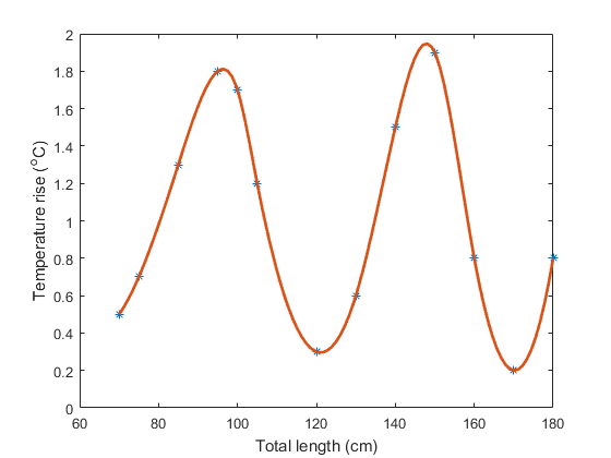
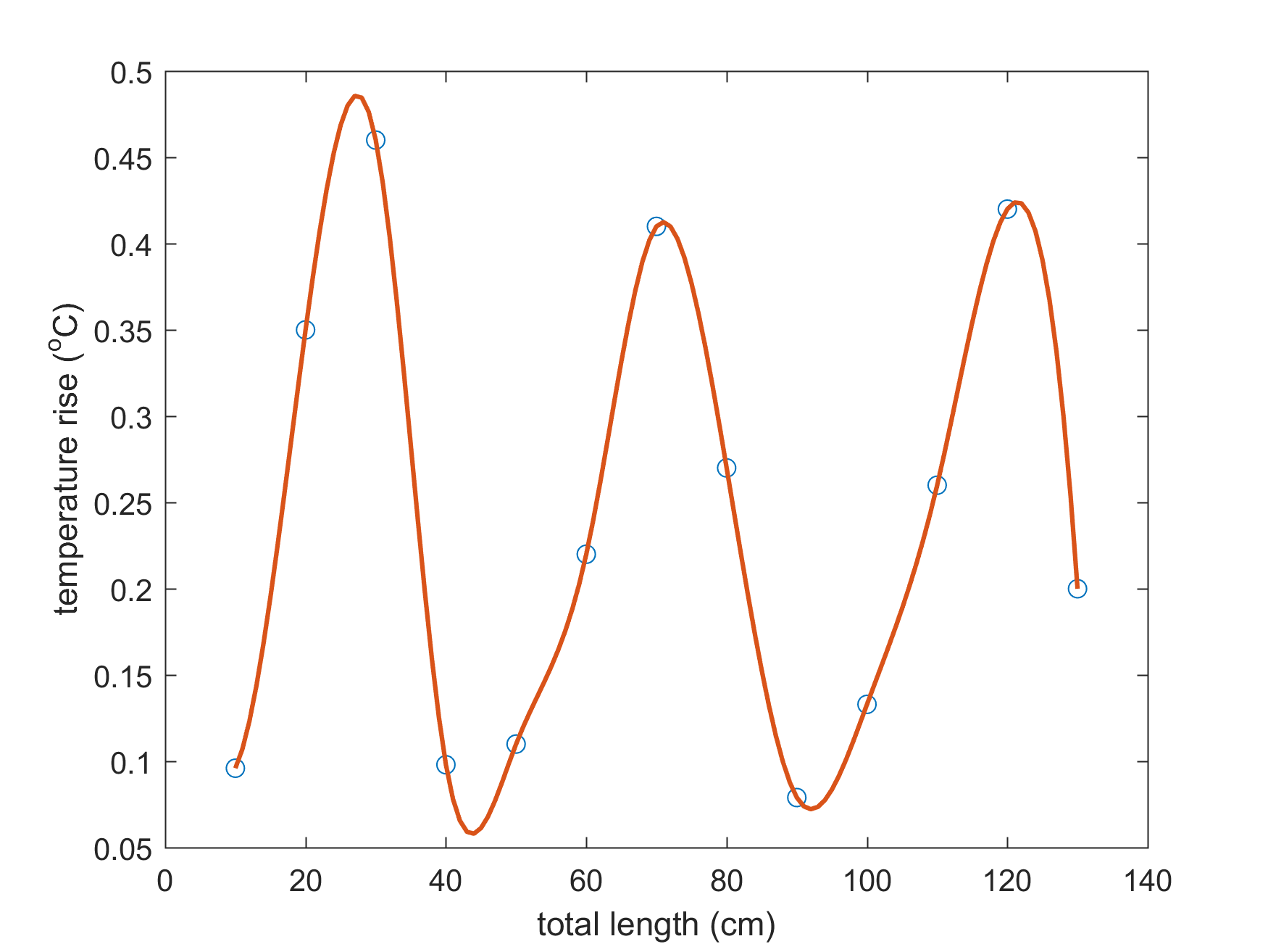
The experimental temperature at the wire tip in gel at different total wire lengths are shown in Fig. 3, which shows a heating behavior wth maximum and the minimum temperature rise happening at certain lengths (resonant and antiresonant lengths respectively) as was reported at 3T.5 The two resonances, determined from the local maxima, were at total lengths of 95 and 145 cm. Separation between the resonances was 50 cm, which is half the wavelength (λ) in air at 7T. Although measurements were not made with total length shorter than 70 cm (due to difficulty in cutting off the wire at shorter lengths), an extrapolation of the periodic behavior suggests the 1st resonant condition to be at a total wire length of 45 cm total length, which is close to the length of an unconnected SEEG electrode (usually 35 cm long); this is predictive of larger RF heating when the SEEG electrode is left unconnected. The simulation results are shown in Fig. 4, which is in agreement with a separation of 50 cm between successive resonance lengths. The slight difference in experimental and simulation temperature changes is likely due to some differences in the properties of the coils (exact geometry, location of the rungs etc.), and the gel (dielectric property etc.) used in the 2 cases. The simulation resonance lengths are systematically ~25 cm less than observed experimentally. The 1st resonance length of 25 cm obtained from simulation is at ~λ/4 at 7T, which is in accordance to that observed at 3T.5 Even though we cannot explain the discrepancy between experiment and simulation, it is important to note that for comparable SAR values (2.7 vs 2.8 W/kg at 7T and 3T respectively), the heating at resonant lengths observed at 7T in this study is significantly lower than at 3T.5Conclusion
The heating pattern of a partially immersed conducting wire at 7T shows a periodic resonance pattern, separated by λ /2 in air, similar to that at 3T. For same SAR, the temperature rise at resonance lengths at 7T is 3-4 times smaller than that reported previously at 3T.Acknowledgements
Cleveland Clinic Foundation Epilepsy Center.
References
1. Armenean C, Perrin E, Armenean M, Beuf O, Pilleul F, Saint-Jalmes H. RF-induced temperature elevation along metallic wires in clinical magnetic resonance imaging: influence of diameter and length. Magn Reson Med. 2004;52(5):1200-1206.
2. Yeung CJ, Karmarkar P, McVeigh ER. Minimizing RF heating of conducting wires in MRI. Magn Reson Med. 2007;58(5):1028-1034.
3. Bhattacharyya PK, Mullin J, Lee BS, Gonzalez-Martinez JA, Jones SE. Safety of externally stimulated intracranial electrodes during functional MRI at 1.5T. Magn Reson Imaging. 2017;38:182-188.
4. Carmichael DW, Thornton JS, Rodionov R, Thornton R, McEvoy AW, Ordidge RJ, Allen PJ, Lemieux L. Feasibility of simultaneous intracranial EEG-fMRI in humans: a safety study. Neuroimage. 2010;49(1):379-390.
5. Bhusal B, Bhattacharyya P, Baig T, Jones S, Martens M. Measurements and simulation of RF heating of implanted stereo-electroencephalography electrodes during MR scans. Magn Reson Med. 2018;80(4):1676-1685.
6. Sammet CL, Yang X, Wassenaar PA, Bourekas EC, Yuh BA, Shellock F, Sammet S, Knopp MV. RF-related heating assessment of extracranial neurosurgical implants at 7T. Magn Reson Imaging. 2013;31(6):1029-1034.
7. Feng DX, McCauley JP, Morgan-Curtis FK, Salam RA, Pennell DR, Loveless ME, Dula AN. Evaluation of 39 medical implants at 7.0 T. Br J Radiol. 2015;88(1056):20150633.
8. Taflove A, Hagness SC. Computational electrodynamics: the finite-difference time-domain method. Norwood, MA: Artech Hhouse; 2005.
Figures