1453
Decoupling circuit design for multi-nuclear RF coil1Philips Healthcare, Pewaukee, WI, United States
Synopsis
The demand about invivo multi-nuclear MRI/MRS has increased
according to introduction of higher tesla MR system. The development of the dual
frequencies RF coil array keeps pace with this interest. At the overlay of both the proton and second-nucleus frequencies coil loops, inductive
coupling between coils has resolved to retain proton sensitivity and coil
tuning stability by LLC and LC tank circuit. However, they cause another mutual
coupling issue between the circuits and coil loops. Therefore, we introduce a simpler
and more efficient decoupling method than LLC and LC tank circuit in this study.
Introduction
The demand for invivo multi-nuclear MRI/MRS has increased according to introduction of high tesla MR system. The high resolution 23Na MRI present by multi channels array is the representative example. At the overlay of both the proton and second-nucleus frequencies coil loops, inductive coupling between coils must be mitigated to retain proton sensitivity and coil tuning stability. The LC or LLC tank circuit placement of multinuclear RF coils have maintained inter-element isolation1-2. However, this trap circuit is lack of high enough blocking impedance or causes another mutual coupling between the trap circuit and the loop coil tuned at proton frequency, which leads proton loop coil tuning to make difficult. In the study, we introduce the alternative decoupling method using LC series circuit. It proves effective through the current density on the sodium coil tracer as well as B1+ field profiles by proton frequency current couplingMethod
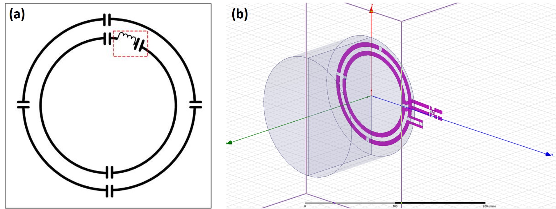
Our approach preventing from coupling by the higher frequency is to add the LC series circuit on the loop tracer for x-nucleus frequency ad shown by figure 1(a). The impedance of the LC series circuit is matched to selectively block current induced at the proton frequency while minimizing the coil sensitivity at the lower x-nucleus frequency. It is simply calculated as the equation (1-2). The series resistance (Rs) by the extra components, especially the inductor, to the low frequency coil causes slight drop of the coils’ sensitivity. However, it is adjustable by change of the total blocking impedance determination for the proton frequency.
$$$Z_{p} = R_{s} + jX_{L} + 1/jX_{c} \approx$$$ high reactance at the proton frequency (1)
$$$Z_{x} = R_{s} + jX_{L} + 1/jX_{c} \approx$$$ zero reactance at the x-nucleus frequency (2)
To verify our proposal, we designed a pair of coplanar concentric loop coils to simulate the current distribution on the copper loop tracer and B1+ field flux induced in a numerical phantom with HFSS (ver.15.0, Ansys.Inc, USA). The inner loop coil (10cm outer diameter, 0.5cm width, 1mil thickness) is tuned at the sodium (33.8MHz) and the outer loop coil (12cm outer diameter, 0.5cm width, 1mil thickness) is targeted at the proton (127.7MHz) for 3T MRI. The coil geometries are driven by Eigen mode with 1W source. 22AWG hand-wound inductor (2929SQ series, Coilcraft, USA), as the decoupling inductor, is used with the series resistance (Rs). Two buildable hand-wound inductors (508nH and 960nH) with high Q-factor (150) at the sodium frequency are determined on the equation (1-2). After, the proton blocking impedances are easily derived as 380ohm and 720ohm. To generate B1 field, the numerical phantom, the conductivity ($$$\sigma$$$) of 0.719s/m and the relative permitity ($$$\epsilon_{r}$$$) 63.5 referred as the muscle tissue, dimensions 14cm diameter and 10cm height. It is nested 0.5cm above the coils surface (figure 1b). On the pair of coplanar concentric loop coils, our concept is competed to no-decoupling and LC & LLC tank circuit presented from previous studies. The frequency response (S11) of each loop coil, electric current density (J) flowed on the coil surface, B1+ field induced into the phantom are analyzed while these decoupling circuits are employed on the coils.
Results
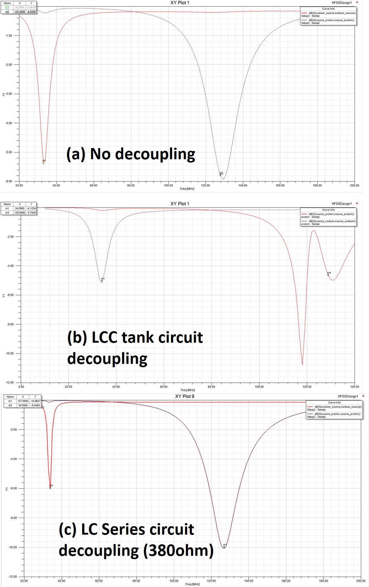
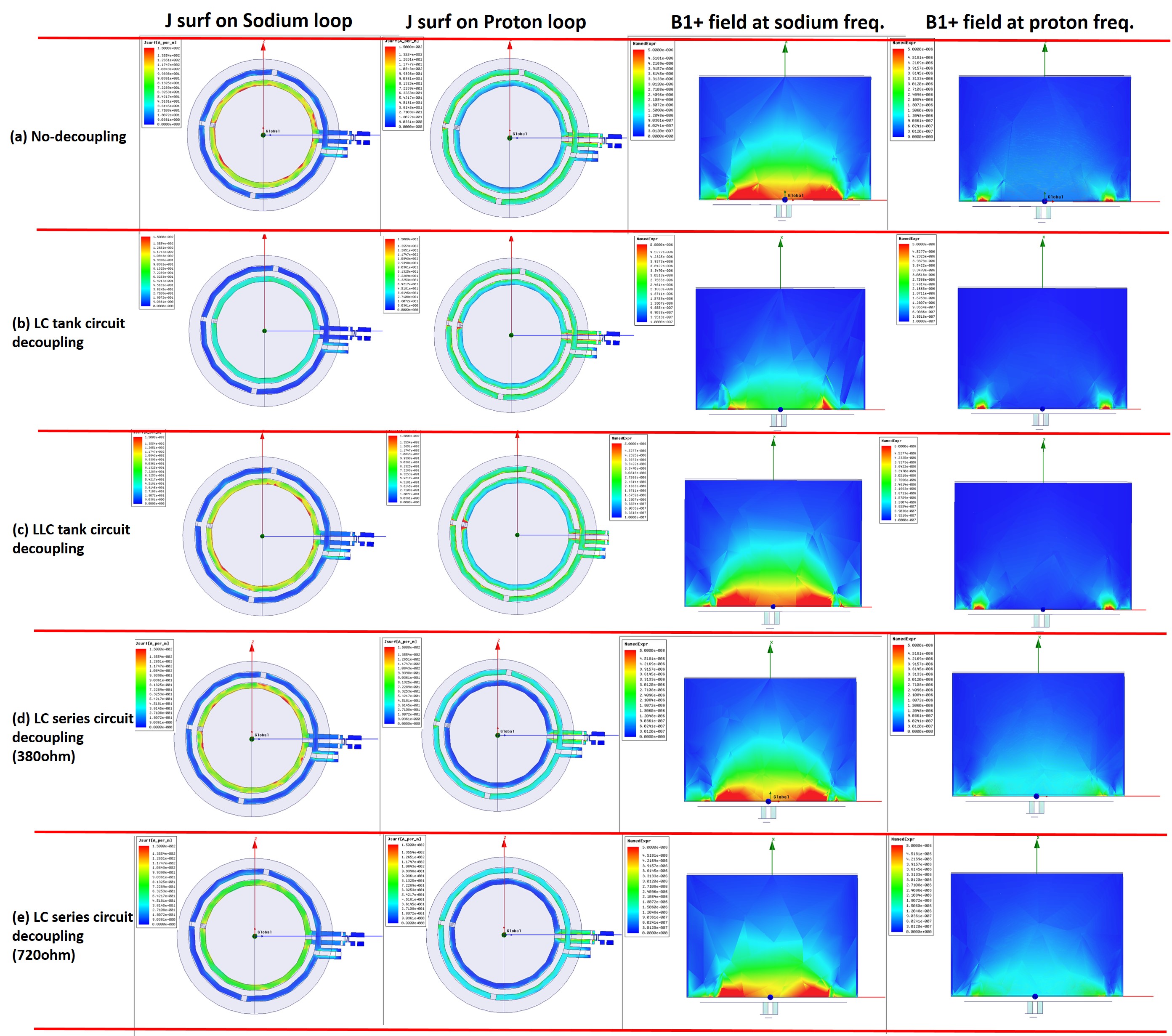
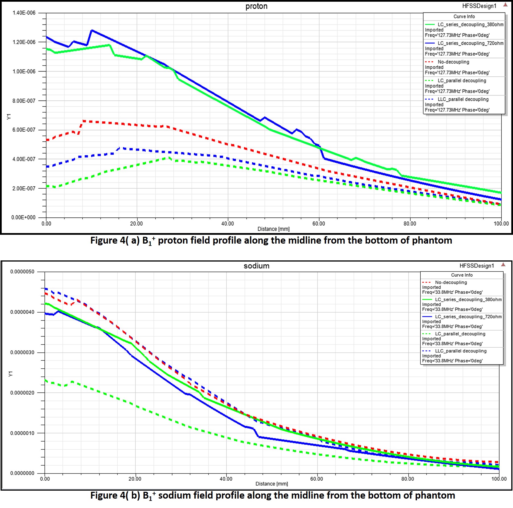
At S11 measurements implementing with/without decoupling circuits, we recognized LC series circuit efficiently decoupled the sodium loop coil from the proton loop coil while both LCC and LC tank circuits created coupling (figure 2). Since the well-isolated frequency response is clearly contemplated through the current density distribution on the coils pair. It made the signal proton loss by no decoupling completely recovered at the point of view of B1+ field in the phantom. By contraries, Both LCC and LC tank circuits produced worse signal cancellation than even no decoupling (figure 3). Rs by the hand-wound inductor caused Q drop of the sodium loop coil but it resulted in only about 5.0% B1+ sodium frequency field degradation up until 20mm above from the bottom of phantom in comparison to LLC circuit and the sodium field profiles by both LC series and LLC tank circuit were equivalent after 20mm (figure 4).Discussion/Conclusion
We successfully demonstrated the new decoupling concept through the comparison to ones researched previously. LC series decoupling circuits can prevent the collapse of proton frequency field at the pair of coplanar concentric loop coils construction. The field sensitivity drop at multi nucleus frequencies fields can be minimized by blocking impedance reduction or hand-wound inductor gauge increment. This concept is useful for the multi channels-multi nuclear array coil owing to simple implement without coupling between LC circuits and proton loop coil. Furthermore, we anticipate that it will be more efficient on higher frequency fields since Q-factor of a hand-wound inductor improves at higher frequency.Acknowledgements
No acknowledgement found.References
1. M. Meyerspeer et al., Magn. Reson. Med. 72:584-590, 2014.
2. J.V. Rispoli et al., Concepts in Magn Reson.46B:4:162-168, 2016.
Figures