1452
Optimization of 4-Port Asymmetric Elliptical Birdcage RF Coil for 1.5 Tesla MRI1Department of Biomicrosystem Technology, Korea University, Seoul, Korea, Republic of, 23Research Institute for Advanced Industrial Technology, Korea University, Sejong City, Korea, Republic of, 3Coretech Co., Ltd., Gyeonggi-do, Korea, Republic of, 4Department of Electronics and Information Engineering, Korea University, Sejong City, Korea, Republic of, 5ICT Convergence Technology Team for Health & Safety, Korea University, Sejong City, Korea, Republic of, 6Corresponding Author, ohch@korea.ac.kr, Seoul, Korea, Republic of
Synopsis
The elliptical whole-body radiofrequency (RF) coil can be used for RF transmission/reception in magnetic resonance (MR)-guided treatment or MR-fused system with space between the RF shield and the gradient coil available for other imaging/treatment modality. The elliptical birdcage has higher B1+ field uniformity than circular birdcage due to increased filling factor between the RF coil and target. In this work, the asymmetric elliptical birdcage is proposed to improve overall performance through electromagnetic simulations. This work compares the 2-port and 4-port excitations and their effects on B1+ field uniformity and SAR deposition for both circular and elliptical coil with symmetrical/asymmetrical structures.
Introduction
The elliptical birdcage RF coil was initially reported in pediatric MR imaging to increase the field uniformity of small target region1. The elliptical shape can improve the field uniformity by increasing the filling factor between the RF coil and target. Optimal current distribution is required to implement an elliptical configuration2. When the whole-body RF coil configuration is considered, the gap between RF shield and RF coil in major-axis becomes very small, and their respective B1+ field distributions become non-uniform. To solve this problem, asymmetric high-pass elliptical birdcage was proposed in this work by optimizing the position of the birdcage legs. Electromagnetic (EM) simulations were performed for evaluation and comparison with high-pass circular and symmetric elliptical birdcage coils. 4-port excitation has been reported to have a higher uniform field distribution when considering large RF coils3. This work compared the 2-port and 4-port excitations and their effects on field uniformity and SAR deposition.Methods
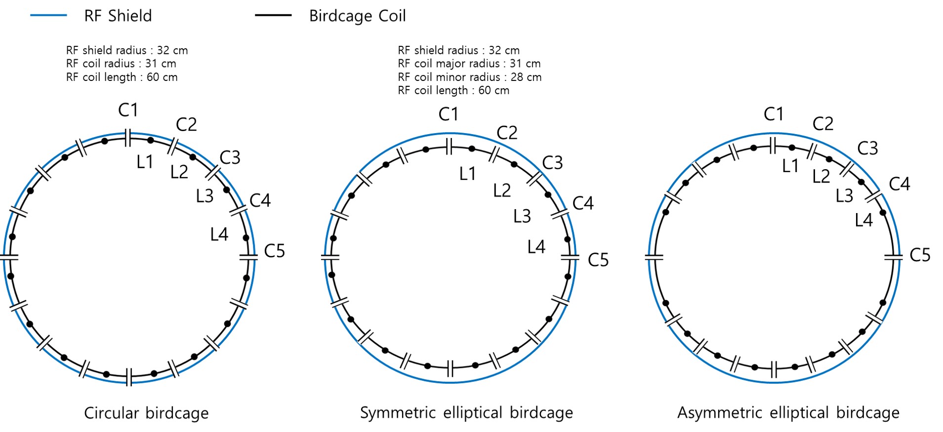
In symmetric elliptical birdcage, all legs are equally distributed in angular direction, and their B1+ field distributions do not seem to provide sufficient uniformity even for elliptical subjects. To improve the uniformity, asymmetric elliptical birdcage is introduced by shifting the legs near the RF shield to the optimum position, and each capacitance is calculated and implemented for EM simulations. Figure 1 shows the circular, elliptical symmetric, and asymmetric birdcage designs and their dimensions. To calculate the optimum end-ring capacitor, the elliptical birdcage theory (eq.1~5) is implemented to calculate the total inductance and impedance of each leg and end-ring segments including the mirror elements due to the RF shield4.
The optimum current distribution, $$I(θ)=\frac{I_0B^2 cos(θ))}{B^2 cos^2(θ)+A^2 sin^2(θ)}$$ (1)
where A and B are the radius of major- and minor-axes, respectively, and is the angle of each leg position.
The self-inductance, Lα,α, of the end-ring segment, $$ L_{α,α}=2l\left[ln\left(\frac{2l}{w+t}\right)+\frac{1}{2}\right]$$ (2)
where l, w, and t are the length, width, and thickness of the rectangular conductor, respectively.
The mutual inductance, Ln,m, between two legs, $$L_{n,m}=2l\left[ln(\frac{l}{d}+\sqrt{1+\frac{l^2}{d^2}})-\sqrt{(1+\frac{d^2}{l^2 })}+\frac{d}{l}\right]$$ (3)
where d is the distance between two legs in centimeters and l is the length of leg.
The total impedance of each leg, Zn, and the total impedance of one end-ring segment, Zα, are calculated as $$Z_n = \sum_{m=1}^{16} \frac{I_m}{I_n} j\omega L_{n,m}+\sum_{m=1}^{16}\frac{I_{m^{'}}}{I_n} j\omega L_{n,{m^{'}}}$$ and $$Z_\alpha=\sum_{\beta=1}^{16}\frac{I_\beta}{I_\alpha}j\omega L_{\alpha,\beta}$$ (4)
Finally, the optimum capacitor, Cα, is calculated as, $$V_n-V_{n+1}=I_α\left[\frac{1}{jωC_α}+Z_α\right]$$ (5)
where $$V_n=\frac{1}{2}I_nZ_n$$ (using Ohm’s law).
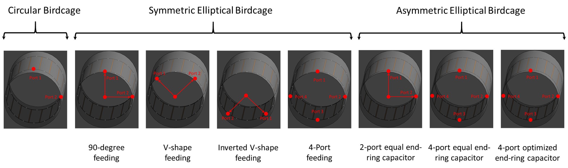
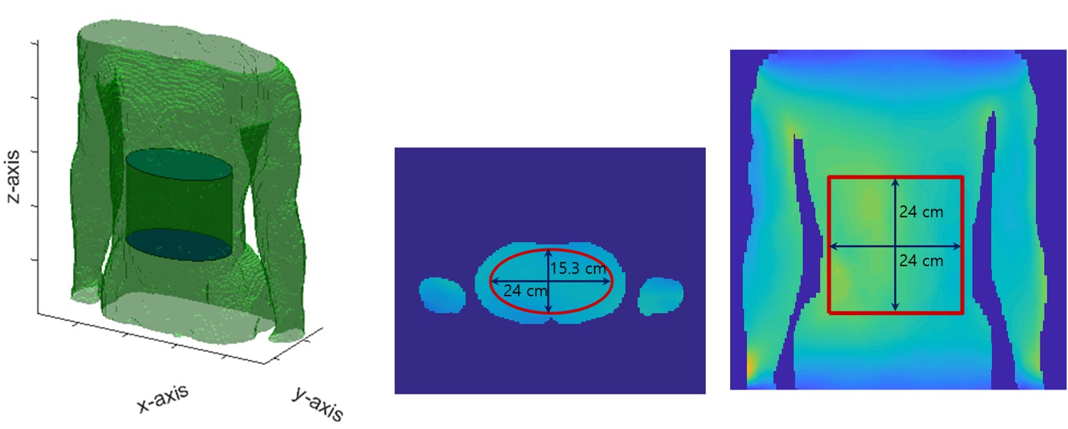
EM simulation analysis based on finite-difference time-domain (FDTD) method was performed using Sim4Life V4.0 in 3-dimensional (3D) human model5,6. Then, through the EM simulation platform, B1+ field distribution, SAR distribution, and total power required are evaluated and compared. For the reference, the circular birdcage is implemented with the identical length and number of legs. In addition, 4- port excitation was evaluated and compared with 2-port excitation. Figure 2 shows the configuration of simulated birdcage coils evaluated and compared in this work. After the EM simulation, B1+ field uniformity is measured using the National Electrical Manufacturers Association (NEMA) standard in the 3D region of interest (ROI) described in Fig. 3. The SAR averaged over any 10g of tissue in the shape of a cube (10g-avg SAR) and total power normalized to 1 µT are calculated to ensure that the SAR is under the safety limits provided by regulatory board.
Results & Discussion
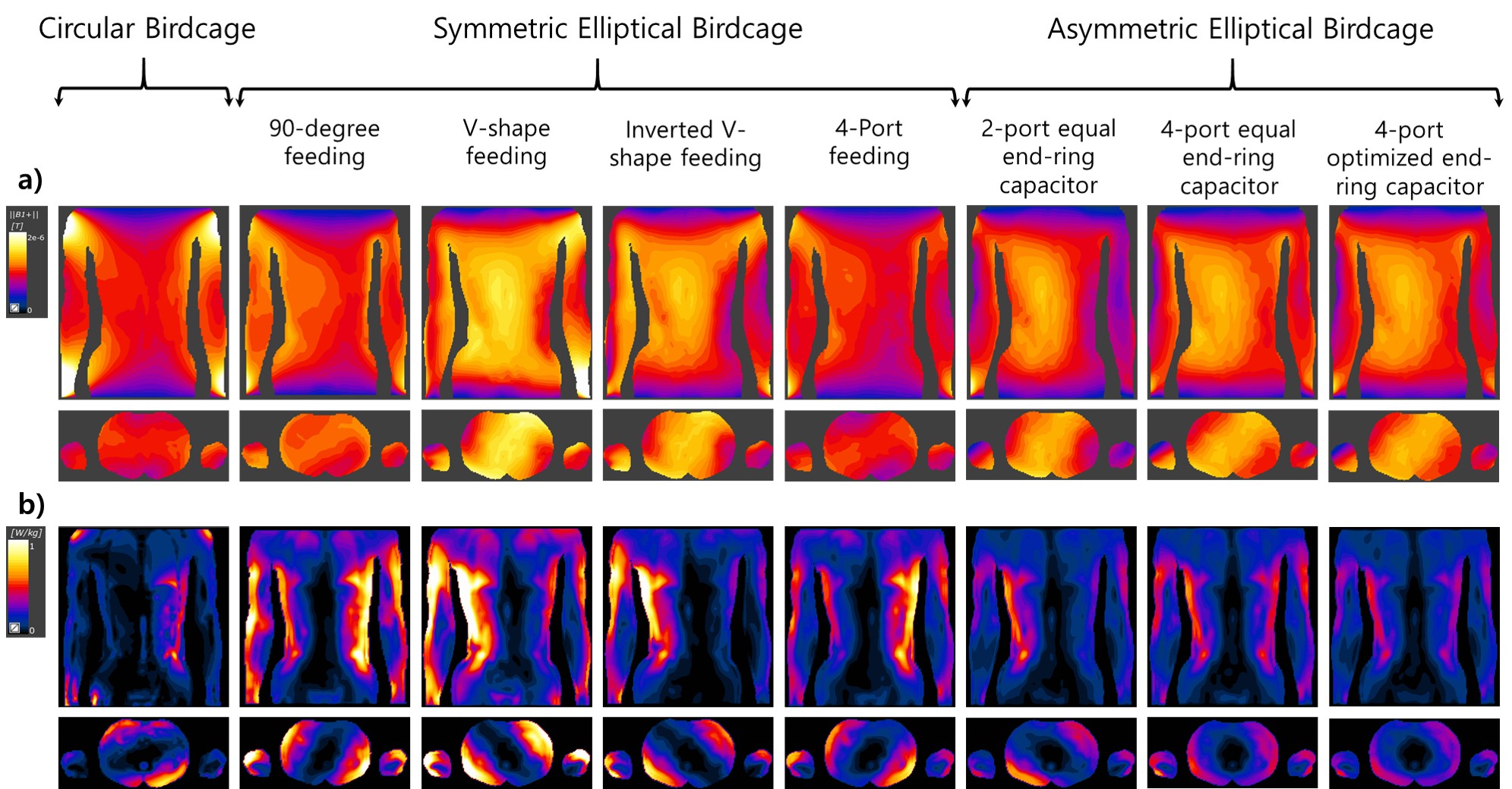
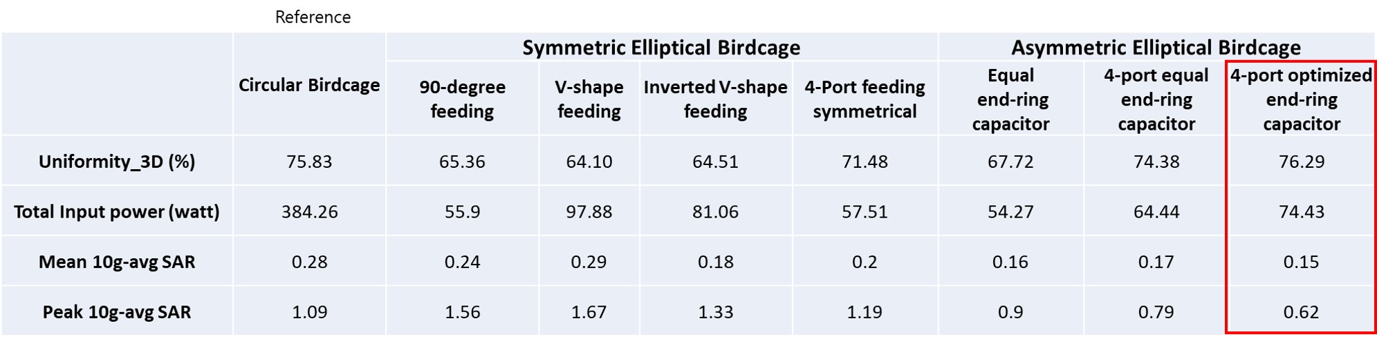
All RF coils were tuned and matched to 63 MHz (proton) using Sim4Life matching toolbox. Figure 4 shows the B1+ field distribution and the SAR distribution in coronal and axial planes for the mentioned RF coils in Fig. 2. Although the symmetric elliptical birdcage was shown to be worse than those of the circular birdcage, the optimized asymmetric elliptical birdcage shows the highest B1+ field uniformity and the lowest 10g-avg SAR. When the optimized asymmetric birdcage is compared with circular birdcage, the uniformity is better, and the SAR and total input power are reduced by 47% and 80%, respectively. Also, the implementation of 4-port excitation improves the uniformity by approximately 10 % compared to 2-port excitation. Table 1 shows the B1+ field uniformity, total power, and mean & peak 10g-avg SAR (normalized to 1 µT) for all simulated coils.Conclusion
In conclusion, the optimization of asymmetric birdcage RF coil was performed for increasing the B1+ field uniformity. The 4-port asymmetric birdcage coil shows the highest performance in uniformity and SAR. In all simulations, the amplitude and phase difference between each port were kept constant. If necessary, RF shimming optimization can be implemented for optimizing the B1+ field uniformity more. In future work, this optimized asymmetric birdcage coil will be verified experimentally in both phantom and in-vivo studies.Acknowledgements
This work was supported by the Technology Innovation Program (#10076675) funded by the Ministry of Trade, Industry Energy (MOTIE, Korea).References
- Kurczewski R, et al. Design of elliptically shaped quadrature pediatric body coils. ISMRM. 1992; 4025.
- Li CS and Smith MB. Theoretical calculations of the optimum current distribution for an elliptical birdcage RF coil. ISMRM. 1993; 1342.
- Ibrahim TS, et al. Comparison between linear, quadrature, and 4-port excitations from 1.5 T to 4.7 T. ISMRM. 1999; 423.
- Li S. et al. A method to create an optimum current distribution and homogeneous B1 field for elliptical birdcage coils. Magnetic resonance in Medicine. 1997; 37(4): 600-608.
- Sim4Life, ZMT, <http://www.zurichmedtech.com>.
- Gosselin MC, et al. Development of a new generation of high-resolution anatomical models for medical device evaluation: the Virtual Population 3.0. Physics in Medicine & Biology 2014: 59(18): 5287.
Figures