1447
An electronically tunable X-nuclei surface coil with high impedance broadband LNA1Experimental Cardiovascular MRI, Ulm University Medical Center, Ulm, Germany, 2GM, Sirona Dental Systems, Bensheim, Germany, 3GME, Sirona Dental Systems, Bensheim, Germany, 4Institute of Smart Sensors, University of Stuttgart, Stuttgart, Germany
Synopsis
In this approach, we present an electronically tunable surface coil in combination with a high impedance broadband LNA for X-nuclei MRI experiments with a bandwidth between 34MHz and 104MHz. The performance of the approach was evaluated by comparison with a state of the art LNA / surface coil reference setup for hydrogen and fluorine imaging. The resulting SNR reduction was less than 4% and a mean value and standard deviation of the relative error of the sensitivity map between the reference setup and the proposed setup of µ=0.4% and σ=1.4% was observed.
Introduction
MR imaging of nuclei other than hydrogen (X-nuclei MRI) has seen tremendous advances over the past decade. Nevertheless, tuning and matching of these coils (arrays) can be time consuming and difficult in practice, since tuning and matching are load dependent [1]. In this contribution, we present a new approach towards X-nuclei MRI that is based on a rapidly electronically switchable surface coil design in combination with a custom designed broadband high impedance pre-amplifier, whose bandwidth covers the Larmor frequencies of all nuclei of interest. To verify the proposed approach, images of CuSO4 and C15F30O5 phantoms have been acquired with the proposed setup and compared to images acquired with a state-of-the-art single-frequency receive chain.Methods
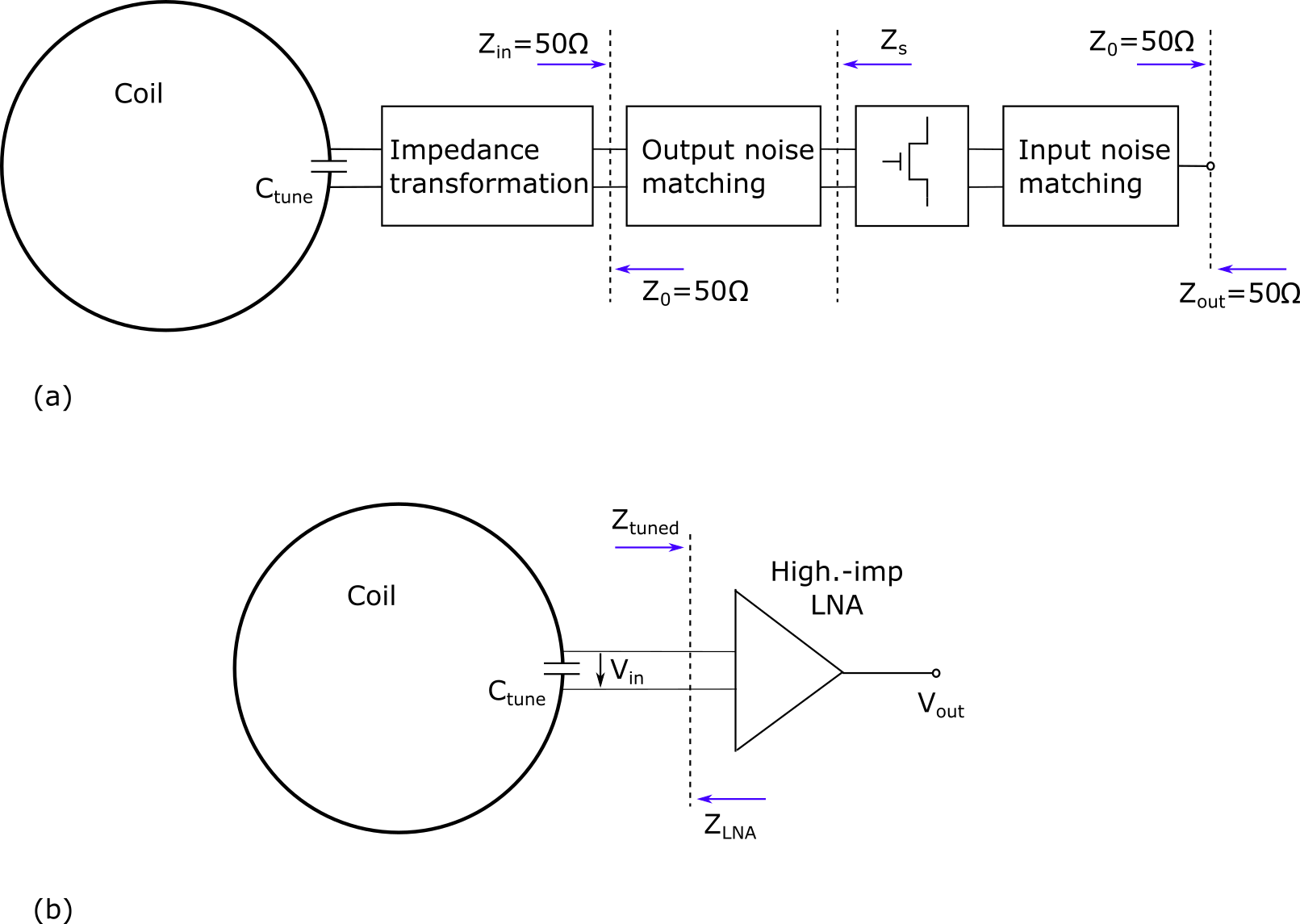
Conventional MRI low noise amplifiers (LNA) are designed using the architecture illustrated in Fig. 1a [2]. A very low noise transistor is used, and the noise figure (NF) and gain are optimized by two passive matching networks (one at the input, one at the output of the transistor). A third matching network is used between the coil and the noise matching network to realize either a 50Ω- or a low input impedance. Since these three matching networks display a narrowband characteristic, all have to be adapted to match the respective resonance frequency in case of X-nuclei imaging.
Our custom-built high-impedance LNA architecture shown in Fig. 1b can easily be applied for broadband (and thus X-nuclei) receive chains, since only a single capacitor Ctune has to be changed for tuning the coil (setup) to the different Larmor frequency. As tuning capacitor the digitally programmable capacitor NCD2100 (IXYS, CA, USA) is used, providing a noise-free pre-amplification of both, the signal and the noise level of the coil, relaxing the burden on the noise performance of the high-impedance LNA.
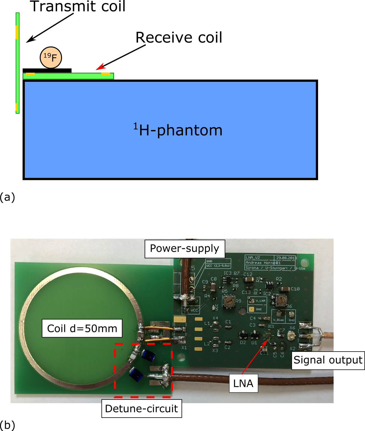
The X-nuclei MRI capability of the proposed high-impedance broadband LNA is demonstrated using the experimental setup illustrated in Fig. 2a. The printed circuit board (PCB) of the receive coil with a diameter of 50mm and the high-impedance LNA is shown in Fig. 2b. The 1H-phantom filled with CuSO4 and NaCl has a dimension of 225mm x 195mm x 85mm. The distance between the coil and the 1H-phantom is about 10mm. Above the receive coil, an additional cylindrical 19F-phantom is placed, filled with C15F30O6. As shown in Fig. 2a, a separate transmit coil for the 19F and 1H measurements is located to the left of the 1H-phantom. All measurements were performed on our custom built MR-Scanner with a B0-field strength of 1.43T, resulting in a Larmor frequency of 57.3MHz for 19F and 61.0MHz for 1H, respectively.
For comparison, all measurements were performed with the proposed high-impedance LNA setup and a state-of-the art 50Ω LNA (reference setup), as illustrated in Fig. 1a.
Results
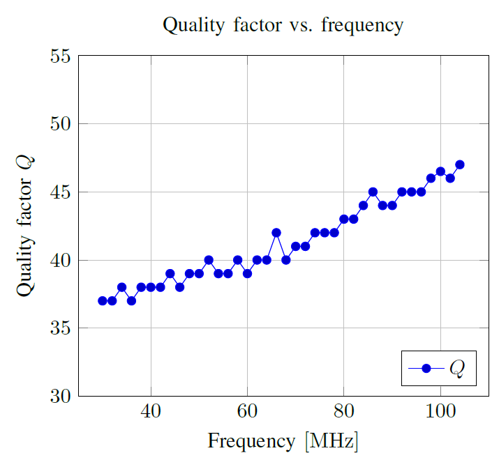
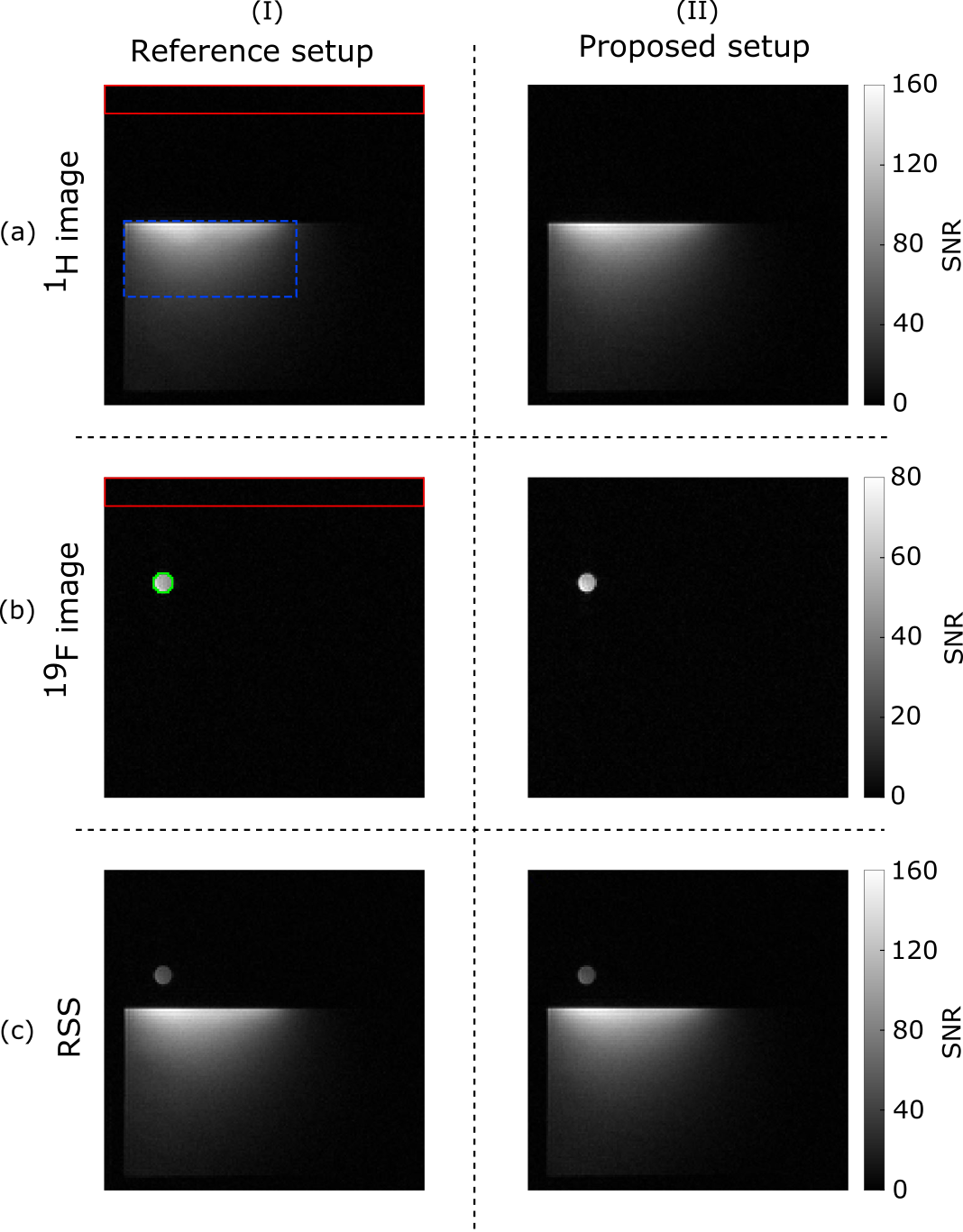
The operational range of the presented setup is from 34MHz to 104MHz with a resolution of 1024 steps. Its tuning can be changed within 60μs. The loaded quality factor Q of the setup is about 40, both at 61.0MHz and 57.3MHz (reference setup as well as the proposed broadband high-impedance setup). The Q-value of the overall operation frequency range is provided in Fig. 3. The measured 1H image of the proposed setup is shown in Fig. 4a(I). A peak SNR value of 160 (proximity to the coils surface, average SNR within the ROI = 44.5) was measured. Fig. 4a(II) shows the respective 19F image with an average SNR of 75.3 inside the ROI. The superimposed MR image of the proton and fluor phantom is shown in Fig. 4a(III). The corresponding images measured with the 50Ω LNA reference setup are shown in Fig. 4b(I-III), resulting in an average SNR of 45.3 for the 1H image and an average SNR of 76.4 for the 19F image, respectively.Conclusion
In this contribution, tuning of the coil over a wide range of nuclei by a switchable coil tuning capacitor in combination with a broadband high impedance LNA has been introduced. The performance of the proposed approach was compared with a state-of-the-art single-frequency tuned receive chain. The almost unaltered SNR performance of both setups prove the feasibility of the proposed approach. Even though the current frequency range (34MHz to 104MHz) is not well suited for X-nuclei imaging at 1.43T, the advantage of the digitally switchable coil setup in combination with a wide-band LNA has been shown, and in combination with different of multiple capacitor arrays, the operational range as well as the accuracy of frequency selection can be further improved.Acknowledgements
No acknowledgement found.References
[1] X. Cao et al., The design of a low-noise preamplifier for MRI, Science China Technological Sciences, 2011, vol. 54, no. 7, p. 1766–1770.
[2] L. T. Muftuler, G. Gulsen, K. D. Sezen, and O. Nalcioglu, “Automatic tuned MRI RF coil for multinuclear imaging of small animals at 3T” Journal of Magnetic Resonance, vol. 155, no. 1, pp. 39–44, 2002.
Figures